
Case study: Designing for rugged thermal management to meet military needs
StoryDecember 09, 2010

Dave Turner
Curtiss-Wright

As military programs continue to push the limits of computing system requirements, rugged computer systems must continue to evolve to endure the toughest conditions: extreme temperatures, shock, vibration, and humidity amidst altitude, fungus, salt fog, explosive decompression, immersion, and sand/dust exposure. To meet these stringent requirements, rugged subsystems suppliers must produce innovative thermal management technologies that can withstand situations that may threaten a computer?s durability. A case study of a U.S. Navy Special Ops river craft is presented to illustrate the inner-workings of a thermal management scheme.
Thermal management remains a major component of any rugged electronic design, as heat issues are often the largest contributors to failures. Consequently, advances in thermal management will continue to rank as one of the most important trends in rugged computing design because processors continue to change along with the demand for higher processing capabilities, including multicore computing at speeds of 1.5 GHz or greater.
While many applications can still be served by energy-efficient single-core processors, new technology developments are demanding higher processing power with low power consumption. Ultra-low power Intel Atom processors cannot satisfy performance requirements in all cases. Consequently, multicore processing technology is seeing a significant boost in deployment within stand-alone rugged boxes. For demanding applications, mobile Core 2 Duo or Core i7 processors, as examples, provide attractive solutions. While presenting a challenge to manage the 10-55 W of Thermal Design Power (TDP) of these processors, they offer a level of performance that pushes the boundaries between traditional rugged computing and new tactical applications. Meanwhile, the following case study examines the thermal management of a multicore mission computer utilizing an Intel Core 2 Duo CPU.
Navy application prompts new thermal management design
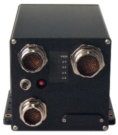
Parvus engineers were tasked with engineering a passively cooled solution that met the increased thermal demands of a multicore processor, upon receipt of a contract to design a specialized version of the DuraCOR 810-Duo mission computer for a U.S. Navy special operations river craft (Figure 1). This specific military customer required a shipboard mission computer as part of its command, control, and communications system designed to operate in an ambient operating temperature of up to +71 °C per the requirements of MIL-STD-810G.
Figure 1: The DuraCOR 810-Duo is a rugged multicore mission-processor subsystem designed for high-reliability applications requiring MIL-STD-810G environmental compliance.
|
|
Unlike Parvus’ legacy-generation mission computer based on a Pentium M processor, this new mission computer integrated an Intel Core 2 Duo CPU – which consumed about 60 percent more power and generated significantly more heat. The challenge for engineers was to design a rugged mission computer with integrated application-specific payload cards capable of cooling a multicore processor in an environment that can only support cooling by natural convection and possibly operate in a stagnant air environment.
Heat pipe not enough for increased thermal demands
To manage the thermal increase in the new mission computer, engineers initially designed the internal subsystem with an integrated heat pipe: a thermal management device that transfers heat by the evaporation and condensation of an internal fluid. Heat pipes didn’t rely on any moving parts to dissipate heat from the system, plus they had been used successfully in the past for other single-core CPU system designs. Heat pipes are also well known for how quickly they can wick heat away from system hot spots. The heat pipe contained a copper outer layer with a hollow center that contained a wicking mechanism. The center was filled with a liquid capable of vaporizing, such as water, alcohol, ammonia, or methanol. When heat hit the pipe, the pipe converted the liquid to a vapor. The vapor escaped down the pipe and came in contact with the cool side of the heat sink. The vapor then cooled and was condensed back to a liquid where it was absorbed by the wick. This transferred the liquid back down the heat pipe to start the exchange over again (see Figure 2).
Figure 2: The heat pipe thermal management solution transferred heat by the evaporation and condensation of an internal fluid.
(Click graphic to zoom by 1.3x)
|
|

Engineers soon learned that a heat pipe was not going to suffice for this system, as preliminary qualification tests concluded that the computer server was experiencing difficulty when performing system stress testing beyond +65 °C ambient air temperature before the CPU’s die would hit Intel’s rated thresholds. The internal temperature of the heat pipe was exceeding its design limits and the core temperature of the computer system enclosure was approaching +90°C. The heat pipe’s increased temperature would not allow the vapor to cool enough to convert back to a liquid – an event referred to as “saturation.” This heat pipe saturation effectively eliminated continued vapor-to-liquid conversion, halting convection to the exterior of the enclosure. The only effective method of heat transfer was the conduction of the copper pipe from the heat-producing processor to the exterior heat sink interface. This condition reduced the possibilities of the system operating past +65 °C ambient air for extended periods of time.
Structural heat-spreader plate offers improvement
Through initial testing, the suggested engineering answer to this challenge was to introduce a conduction-cooling mechanism through a structural heat-spreader plate. Rather than channeling the heat from the single board computer through a copper pipe and converting the liquid to a vapor, engineers designed an aluminum heat spreader to transfer heat to the exterior chassis heat sink. When the aluminum is exposed to a heat source, the heat is conducted through the metal. Unlike the heat-pipe approach where vapors move very quickly through the pipe, the aluminum takes a slightly longer time to conduct the heat. While the design may suffer slightly in the initial heating cycle, the solid metal “spreader” offers the advantage of not losing its effectiveness by “saturating.”
When the heat reaches the exterior heat-spreader plate, it interfaces with a thermally conductive material, which then transfers the heat to the chassis heat sink. With a high-finned protruding design, these extruded heat sinks increase the surface area of an enclosure housing, transferring potentially damaging heat away from a system and preventing performance degradation. By designing a direct conduction method from the internal heat-producing components to the natural convecting exterior of the enclosure, the heat can continue to move to the ambient air without the risk of saturation, allowing the system to operate in higher temperatures as required by contract: to +71?C.
Though the DuraCOR 810-Duo described was designed for a specific application, other military customers are interested in deploying similar solutions in ground, naval, and airborne vehicles. Accordingly, Parvus intends to apply its lessons learned and similar thermal management analysis to address varying program requirements. Because at 40,000 feet (12,192 meters), roughly one-fifth of the atmospheric pressure (2.7 PSI) is available for convective cooling compared to sea level (14.7 PSI), the COTS dual-core subsystem will be fitted with an optimized heat-spreader plate as the default configuration to maximize application robustness.
Continuous innovation needed for rugged design
Engineers always need to be conscious of which issues are preventing a computing system from reaching its ability to meet a customer’s needs. Gaining a better understanding of which combination of thermal products and techniques help transfer heat while maintaining cost, weight, and system integrity will prove to be one of the most important elements in rugged computing design. This influences chassis and internal package design to accommodate hardware and system design features to manage the heat while still maintaining the unit’s physical integrity and size and weight constraints. Consequently, the ability to analyze requirements quickly and identify potential solutions remains a key skill for the design engineer. As illustrated in the aforementioned case study, thermal engineers should be particularly cognizant of saturation of a heat-pipe design at high temperatures. Not all solutions are the answers to every design problem. Heat pipes are an excellent choice for cooling electronics and will always be one of the top choices for these high-powered applications. Diligent study of every possible alternative is always part of a design engineer’s plan to succeed. Being aware of a component’s limitations adds to that success.
Additionally, engineers should remain current on the best rugged design practices by continuing to expose themselves to several areas of design. By gaining a better understanding of mechanical engineering practices, electronic engineers in particular can better learn how to solve electronics design challenges, especially when dealing with rugged design requirements. The same can be said for mechanical engineers as they are tasked with the rugged packaging of electronics. As customers continue to push the limits of computing system requirements, rugged computer subsystems will continue to evolve to endure the toughest conditions, as long as good engineering practices are implemented and maintained.
Dave Turner is a Senior Mechanical Engineer at Parvus Corporation, based in Salt Lake City, Utah. He has more than 25 years of engineering experience, including development programs of the armed forces in areas such as B-1, B-2, F-117, F-14, A-7, F-22, space environments, missiles, ground vehicles, and shipboard equipment. Dave can be reached at [email protected].
Parvus Corporation 801-483-1533 www.parvus.com


