Understanding the test criteria of optical-fiber transceivers used in space
StoryJune 03, 2019

Justin Lauzon
Reflex Photonics
In electronics used for space and avionics applications, failure is not an option. Components must stand extreme heat, cold, radiation, shock, and vibration, yet deliver reliable performance. To stand up to this kind of harsh use, devices must be tested beyond what is specified to ensure performance in harsh environments to avoid failure. There are a number of essential steps involved in designing a component-test program to ensure reliability and performance.
Components and systems used in space and avionics applications must be able to withstand extreme heat, cold, radiation, shock, and vibration to deliver reliable performance. Finding failures, defects, and marginal components through stringent testing is essential; such thorough vetting leads to products with a long life and high reliability in the field and in space. (Figure 1.)
Figure 1 | A diagram of the possible connections between the causes of parts failure. Connections are indicated with solid lines, while a no-connection state is shown with a dashed line. Preordained failures have an internal mechanism that produces the same outcome – failing at a set rate – from the moment of creation. (Source: AT&T Tech Journal, 1985.)
|
|

The advantages of optical fiber extend to space
Optical transceivers drive the transmission of data, converting signals to and from a copper-resident format. Fiber-optic cables (FOCs), with their high-bandwidth and low-latency signaling, can be used in the punishing space environment to provide immunity to EM/RFI interference, crosstalk, and voltage level surges. The accuracy and reliability of FOCs exceeds traditional cabling: Covering 1,000 feet requires four pounds of FOC, versus 39 pounds of copper wiring, and fiber optics also consume less energy than copper. To convert electrical signals from circuitries with copper output to fiber optics, optical fiber transceivers are usually required.
Let’s use a suitable example: A short-reach parallel multimode fiber-optic transceiver supporting a large bandwidth (up to 28 Gbps/channel). A fact: Intrasatellite communications require a high bit rate; in years past, optical transceivers represented high-performing technology, yet exhibited weakness in harsh environments. However, ruggedized, sealed optical transceivers now survive rocketing into orbit, extreme temperatures, and radiation. Designers and users must test optical devices to ensure quality and reliability.
A variety of tests must be run to ensure that critical devices such as optical transceivers can provide reliable operation in space, including space applications testing (plus radiation), mechanical, environmental, Life Tests, Live Tests, and rigorous screening tests for ensuring the reliability of subsequent lots.
How to perform the five critical tests
In addition to a controlled setup, each test requires visual inspection for anomalies before and after the evaluation. A significant performance degradation associated with a test is considered a qualification failure. For the purposes of this discussion, we are focusing on mandatory testing of fiber-optic transceivers (FOTs) intended for operation in space or a similarly harsh environment. All devices need mechanical and environmental testing to verify long-term integrity. Mandatory tests also include Life Tests and Live Tests. Such tests can help root out design or process flaws. Finally, even if the units pass all of the tests, every subsequent lot of units must undergo screening tests.
Mandatory mechanical and environmental tests
Three consecutive mechanical tests are executed on the same FOTs. Before and after completion of the mechanical-integrity evaluation, units must be visually inspected and characterized over the operating temperature range to confirm that no significant performance degradation occurs. Mechanical-integrity evaluation tests are executed on nonoperating units, in the order below:
Vibration tests across all three axes (20 g between 20 Hz and 2,000 Hz at sixteen minutes per axis).
Mechanical-shock tests of five repetitions each over all six orientations, using 500 g shock on a half-sine pulse duration of 0.5 ms.
Thermal-shock tests consisting of twenty cycles between 0 and 100 °C with 10 minutes dwell time and transient time of less than 5 seconds.
Three environmental stress tests for FOTs include:
A temperature-cycling test to evaluate mechanical fatigue over the component’s lifetime. For example, a mismatch of dissimilar materials subjected to thermal expansion can cause failure.
A damp-heat test to ensure that a sealed FOT can continually provide resistance to a moisture-filled atmosphere.
A sequence of tests, applicable only to products with a BGA [ball-grid array] electrical interface compatible with solder reflow, is performed. These test for possible impact to reflow profile and cold temperature storage.
Life Tests confirm reliability over the lifespan of the product
Life Tests validate long-term reliability via extensive, hastened lifetime tests with several units from different lots. Life Tests are not intended to test for up-front mortality, for which burn-in tests would suffice. Rather, Life Tests forecast performance degradation over a product’s expected lifetime. To emulate operating for more than 20 years, an FOT operates at a bias current exceeding operating condition by 80% for 4,000 hours at a case temperature of 100 °C.
Live Tests evaluate performance
Live Tests, although more complex, thoroughly evaluate the performance of several electrical and optical interface configurations. Live testing is performed with high-speed digital signals operating through every channel of the device under test (DUT). As the DUT is stressed, transmission errors are measured to maintain a bit-error rate (BER) that is better than 1 error in one trillion bits while operating under harsh conditions. Tested under stress, a significant signal degradation of an FOT will demonstrate a cumulative effect from both transmitter and receiver areas that would affect the error count. (Figure 2.)
Figure 2 | Live Test setup configuration. (Image: Reflex Photonics)
|
|

Space applications tests
A major threat in space is radiation. Radiation testing must be split into three different categories for evaluation, covering potential complications related to geostationary or low-earth orbit environments. At least five units should be collected for each test. The tests should be repeated when FOT critical components arrive from new fabrication lots. The radiation tests are:
A nonoperational test with a total non-ionizing dose (TNID) protons (5e12 proton/cm2 total dose).
A live test, single-event effect (SEE), at both room temperature and 85 °C, including heavy ions (Ho, Cu, Ar, Ne, N, each for a total fluence of 1 x 10⁷ ions/cm2).
A biased and unbiased test with total ionizing dose (TID) of gamma rays (100 krad cumulative dose).
The number of errors/events caused by live radiation tests must be compared to those occurring at acceptable levels. For nonoperational tests, the performance of FOTs before and after the application of radiation dosages are compared and can only differ negligibly to pass. A ruggedized FOT that is sealed with encapsulation material must undergo an outgassing test. Live thermal vacuum tests, maintaining a vacuum of at least 5 x 10⁻⁵hPa for at least twenty thermal cycles extending from -40 °C to 85 °C, ramp temperature at ~5 °C/minute, with 5-minute dwell times, must also be successfully completed. Other tests for space applications include decompression tests, which can also be used to qualify parts for avionics applications. Decompression tests demonstrate that performance is not affected at pressure levels emulating a 2,438-meter or 8,000-foot altitude, ramping to 15,850 meters or 52,000 feet in less than 15 seconds and remaining there for one hour. (Figure 3.)
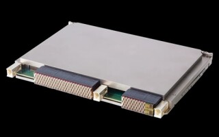
Figure 3 | A highly ruggedized, radiation-resistant optical transceiver suitable for use in satellites. The SpaceABLE28 model has high I/O density with up to 28 Gbps/lane and can handle temperatures from -40 °C to +85 °C. (Image: Reflex Photonics)
|
|

Screening Tests ensure ongoing accuracy
Finally, Screening Tests of six thermal cycles ramping at 8 °C/minute with 5-minute dwell times are completed for continuous assurance of quality commercial off-the-shelf (COTS) devices. Added to thermal cycling is a burn-in with a duration of 168 hours and a case temperature of 100 °C, operating at normal bias current. After a new FOT design is qualified via the aforementioned testing, units from subsequent production lots are validated with the screening process. Temperature cycling tests tend to reveal assembly defects, whereas burn-in tests exhibit infant mortality rates.
Because failure in applications such as space, avionics, and defense is unacceptable, components and systems used in these areas must stand extreme heat, cold, radiation, shock, and vibration to deliver reliable performance. Finding failures, defects, and marginal components through stringent testing is essential and leads to products with a long life and high reliability in the field and in space. Advancing through the five critical tests designed to demonstrate reliability in harsh environments results in fiber-optic transceivers that meet or exceed operational requirements. Such assurance typically outweighs cost-saving considerations for many critical applications.
Jocelyn “Justin” Lauzon is senior technical advisor at Reflex Photonics, Inc. Previously, he was vice president of engineering at the company from 2015 to 2018. Before joining Reflex Photonics, Jocelyn was product line manager and program manager for optoelectronics at avionics subsystems manufacturer CMC Electronics from 2006 to 2015. Jocelyn obtained his Ph.D. in electrical engineering from Université Laval in Quebec. He holds 14 U.S. invention patents and has published more than 75 scientific papers in his career. Readers may reach Dr. Lauzon at [email protected]