Stacked, high-speed DDR4 and DDR5 memory useful in harsh battle environments
StoryFebruary 14, 2019

Jennifer Keenan
Mercury Systems
Today's autonomous and artificial intelligence (AI) military systems process an ever-growing amount of sensor data. To handle this extreme workload, system architects must design boards using the fastest FPGA [field-programmable gate array] devices and Intel multicore processors. These devices cannot provide peak performance without massive amounts of high-speed double-data rate fourth generation (DDR4) memory for resident data and real-time execution.
Faced with huge data asks, architects must engineer their systems to meet the size, weight, and power (SWaP) constraints of smaller, more agile platforms integral to our warfighters’ mission success. To support the system requirements, each embedded board within the system may need a minimum of 64 GB of memory per processor, equating to more than 128 separate commercial-grade memory devices or multiple dual inline memory modules (DIMM) for layout on a printed circuit board.
This is not a feasible solution for the embedded boards inside ultra-compact military systems operating in harsh, forward-deployed environments. High-density, military-grade memory using die-stacking technology must be utilized for space and power savings while maintaining reliability in harsh environments.
The problems are stacking up
The complexity of die stacking and wire bonding increases with each additional die needed to engineer high-density memory, such as a single 16 GB DDR4 device. With so many circuits in a tightly stacked configuration, signal integrity is at the forefront of design considerations. The two main components of compromised signal integrity in the context of this discussion are crosstalk and return loss performance.
- Crosstalk is the unwanted voltage noise coupling due to strong mutual inductance and mutual capacitance. More simply stated, it is the interference to a signal in one circuit caused by the signal transmission in an adjacent circuit in the die stack.
- Return loss is the signal distortion caused by the portion of a signal reflected back to its origin instead of carrying through to the final termination. It is caused by an impedance mismatch or discontinuity in a transmission line.
These performance issues limit data speeds in stacked-memory devices, comprising overall system performance and reliability. In mission-critical military applications, they may also lead to catastrophic events.
Traditional die-stacking design topologies have their limits
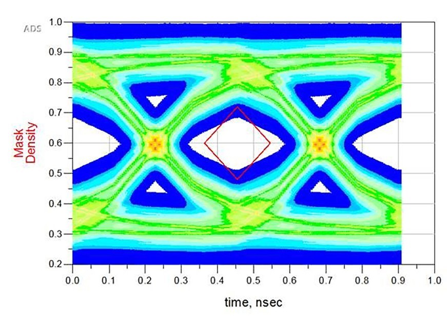
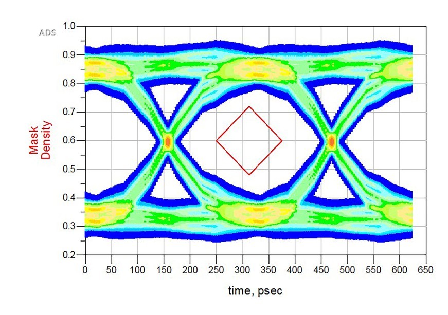
Traditional multichip stacking design methodologies use a branch or star topology. This is an effective design method for DDR2 and DDR3 devices as it enables the required data rates and densities those generations of devices can deliver. (Figure 1.) Skillfully designed stacked DDR4 devices could be feasible with this method. However, there are inherent limitations for high capacities as the increased termination path or bus length causes signal distortion and limits the maximum bandwidth of the transmission line due to reflections. As the number of stacked die increases, these continue to degrade to a detrimental point. Branch topology reaches its maximum capability thereby ruling out this method for use in highly dense, high-speed DDR4 and DDR5 devices. (Figure 2 and Figure 3.) Signal-integrity engineers must look at alternative design methodologies to enable the next generation of smaller, more agile military systems.
Figure 2: 2400 Mbps DDR4 using branch topology.
|
|

Figure 3: 4400 Mbps DDR5 using branch topology.
|
|
High-density DDR4 realized
To reach the high-speed requirements of DDR4, the signal-integrity engineer faces two main challenges: First, reducing crosstalk, prominent with designs using non-transverse electromagnetic (TEM) conduits such as a redistribution layer (RDL) and bond wire; and second, meeting a minimum of -12 dB return loss performance.
Enhancements to the interconnect layer by way of a coplanar topology that supports higher frequency operations than branch topology is needed. This shortens the path between the two terminations while eliminating stubs, consequently improving signal integrity and timing. To achieve this, routing signals sequentially from one die to the next eliminates reflections associated with stubs or extra traces previously seen in branched designs. Creating a contiguous signal return path and linear bus path by adding a microstrip transmission line enables high-speed data rates. Additionally, considerations made to signal and signal-return trace widths further enable higher data rates and improvements to return loss.
With this topology, achieving a return loss of -16 dB through a delicate balance with crosstalk enables the miniaturization of 18 memory devices in a single compact package while offering 2666 Mbps date rates over military temperature ranges. However, while return loss is optimized with this method, improvement to crosstalk performance is still needed to meet DDR5 data speeds. (Figure 4 and Figure 5.)
Figure 4: 4400 Mbps DDR5 using advanced coplanar topology
|
|
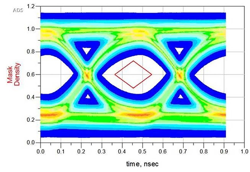
Figure 5: 6400 Mbps DDR5 using advanced coplanar topology.
|
|

The path to military-grade DDR5
With expected double bandwidth and density over DDR4 along with improvements to power and channel efficiency, advanced military systems will use DDR5 devices to increase performance. However, even with the advancements in the coplanar topology for a high-density multichip package previously introduced, the higher data speeds for DDR5 still cannot be attained. Further improvements to crosstalk performance and the inter-die network are necessary. Developing a unique multiplanar ground and signal trace layout applied to the RDL increases crosstalk isolation resulting in a performance improvement of 6dB. No other known die-stacking design methodology is available today for the commercialization of high-density DDR5 in a singular device with data rates as fast as 6400 Mbps. (Figure 6.)
Figure 6: 6400 Mbps DDR5 using advanced multiplanar topology.
|
|
With the DDR5 JEDEC standard still in development, commercial DDR5 devices are set to release in 2019. Military-grade, high-density devices supporting speeds as fast as 6400 Mbps using advanced topology techniques will follow shortly after, set to release in 2020. Designers and users of next-generation military embedded systems will soon realize the maximum performance of their high-speed multicore processing systems due to the integration of high-capacity, high-speed stacked DDR5 while simultaneously benefiting from a much smaller system footprint.
Jennifer Keenan is the Senior Product Marketing Manager for the Microelectronics Secure Solutions group in Phoenix, Arizona. Jennifer has a bachelor’s degree in Marketing from Florida State University. Contact the group at [email protected].
Mercury Systems • www.mrcy.com