SOSA approach using VITA form factors in ATR, SAVE, or rackmount enclosures: The MOSA strategy in support of U.S. warfighters
StoryNovember 11, 2024

Bill Pilaud
LCR Embedded Systems
When designing integrated systems in ATR [air transport rack], SAVE [standardized A-kit vehicle envelope], and 19-inch rackmount enclosures using VITA form factors within the Sensor Open Systems Architecture, or SOSA, framework, the Air Force, Army, and Navy benefit from a superior electronics form factor for all platforms across the U.S. arsenal. The VITA ecosystem offers a wide range of vendors providing CPU, switch, FPGA [field-programmable gate array], GPGPU [general-purpose graphics processing unit], power, RF digitizers, and up-/down-converter solutions. This approach enables systems integrators to develop any C5ISR [command, control, communications, computers, cyber, intelligence, surveillance, and reconnaissance] system by selecting off-the-shelf VITA plug-in cards (PICs) and pairing them with the appropriate enclosure for deployment on military platforms. This flexibility makes SOSA/VITA subsystems the optimal choice for implementing MOSA – the modular open systems approach.
The Open Group’s Sensor Open Systems Architecture, or SOSA, consortium was formed in 2017 as a collaboration of U.S. armed service, tier-one defense primes, academia, and open systems providers with the charter of developing a consensus-based, company-neutral open standard. The SOSA Technical Standard (ratified in fall 2021) was bolstered by the 2019 Tri-Service memorandum on the modular open systems approach (MOSA), in which the secretaries of the Navy, Army, and Air Force Service Acquisition Executive and Program Executive Officers mandated MOSA as a requirement for all future weapons systems for warfighters’ success1.
For the last 40 years, VITA ecosystem providers have been developing components that have increasingly been deployed in embedded systems with a solid track record of performance with optimized size, weight, and power (SWaP). The ecosystem is so pervasive that nearly every platform in the U.S. arsenal has VITA subsystems in one form or another. The SOSA approach, which leverages open standards including VITA form factors, is enabled by enclosure types like SAVE [standardized A-kit vehicle envelope] for Army ground mobile platforms; ATR [air transport rack] for Air Force, Navy, and Army airborne platforms; and 19-inch rackmount for Navy ships and subs.
SOSA or VITA plug-in cards (PICs) are available that meet the operational requirements of any C5ISR application and are intended for these enclosure variants which fit into existing equipment bays. The result is that SOSA/VITA PIC combinations are the optimal logistics solution and offer the best time-to-theater for the U.S. arsenal. Therefore, the SOSA/VITA combination is the best strategy to deploy MOSA electronic subsystems.
What Is SOSA?
The SOSA Consortium is made up of industry and U.S. Department of Defense (DoD) representatives tasked with providing the best open standard to meet the mission needs of the warfighter with the quickest time-to-theater. By leveraging existing standards like MIL-STD, VITA, VICTORY [Vehicular Integration for C5ISR/EW Interoperability], and the Future Airborne Capability Environment, or FACE, Technical Standard, the SOSA Consortium downselects PIC profiles to expedite source selection of plug-in cards. The SOSA approach further improves system-to-sensor or system-to-system communications by defining MIL-STD-1560 connectors, as well as defining pin definition to further improve system integration.
The SOSA Consortium’s vision is to solve a common challenge faced by military platforms: the difficulty of integrating electronic systems that currently rely on different architectures. These challenges include high costs, complex maintenance, and limited industry-wide support for stovepiped solutions. In keeping with MOSA, the SOSA approach seeks to ensure upgradability, interoperability, and interchangeability across all branches of the DoD.
Each single electronic subsystem function – including crew display, APNT [assured positioning, navigation, and timing], and 360-degree situational awareness – is a different electronics subsystem and a potentially different base architecture type. Similarly, the communication radios and the electronic warfare (EW) protection subsystems using similar antenna or sensor arrays cannot swap components and are then single points of failure. Even if these subsystems have the same mount points to the equipment bay, the field-replaceable units (FRUs) in each subsystem are rarely interchangeable. For example, power supplies from one system can never be used in another, so therefore the logistics depot must stock individual systems and FRUs to maintain the platform.
The SOSA approach has standardized on an electronics form factor that has the capability to move electronics subsystem mission into a single or combination of VITA PICs. These VITA PICs are generic but are adapted to mission based on software load.
Therefore, an APNT subsystem can be hosted in a single VITA APNT PIC and cabled to other subsystems based on SOSA defined interfaces. A combination of PICs can be hosted on a backplane to SWaP-optimize electronics deployment. (Figure 1.)

[Figure 1 ǀ A combination of PICs can be hosted on a backplane (center) to optimize SWaP in electronics deployment. Images courtesy LCR Embedded Computing, Wolf Advanced Technology, and U.S. Army.]
SAVE chassis
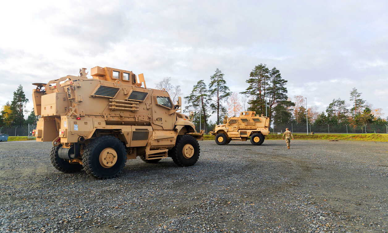
Eventually, for Army platforms, the system integrator can host all electronic subsystems functions of the platform in SAVE, and the system is not only SWaP-optimized but also cost-effective due to minimal logistics cost. SAVE defines the size, weight, power, environmental requirements, connector requirements, and electrical interfaces for C5ISR systems installed in ground combat vehicles.
The SOSA Technical Standard is, however, an 80% specification. Not all innovations, sensors, or deployed systems can be implemented with 100% SOSA aligned components. An example of components not SOSA aligned are backplanes, which can have more than 8 million permutations. The bulk of backplane interconnects, however, such as PIC-to-PIC (slot-to-slot) communication paths are defined via backplane channels such as the data plane, expansion plane and control plane. System-to-system (chassis-to-chassis) connectivity is accomplished via SOSA defined 38999 connectors and pinouts.
The SOSA Consortium has selected three different form factors from VITA: 3U and 6U VPX (VITA 46) and VNX (VITA 90). Moreover, the consortium is looking to new VITA standards to better support next-generation technologies.
What is VITA/VPX?
VITA (VMEbus International Trade Association, https://www.vita.com/) was created in 1984 as the VMEbus industry trade association. The VME standard is a form factor adopted by markets including military, aviation, telecommunications, medical, and industrial manufacturing. VITA would then accredit its standards into the American National Standards Institute (ANSI). In 2003, VPX (VITA 46, 48, 65, 66, and 67) was initiated with the advent of serialized or point-to-point (not bused) technologies. VPX helped define architectures to implement serial fabrics such as RapidIO, PCI Express, and Ethernet as board-to-board communications paths between PICs. VPX quickly became one of the more popular open form factors for military applications, with the result that many major C5ISR subsystems for the Navy, Army, and Air Force use the VPX form factor today.
The reason the system integrators chose VPX over any other open standard was the quick time-to-theater it promised and the fact that the systems were built with ruggedization in mind. REDI [Ruggedized Enhanced Design Implementation, or VITA 48.0] defined mechanical standards for air cooling (48.1), conduction cooling (48.2), air-flow-through (48.8), and air-flow-by (48.7, sealed air cooling). Perhaps even more innovative is that VPX also defined liquid-flow-through cooling in VITA 48.4.
Perhaps the most compelling arguments for VPX are the service features: By combining the different mechanical form factors to adapt the PICs to different platforms, the cards can be built to Level 2 maintenance capability, meaning that these modules can be serviced with protective gloves in the field rather than transported to a maintenance depot. If a module fails, the brigade or platform could maintain a few generic PIC spares to replace failed PICs in-theater. In short, with VPX the subsystem mission electronics can be easily maintained while large, heavy enclosures remain in place.
Repair/replace service time savings is substantial. For example, the time required to service the F-18 radar would go from approximately 18 hours for repair-depot servicing down to 1 hour to perform the service in the field.
Moreover, under VPX there exists an electronics PIC for every mission function. VPX providers have built SBCs [single-board computers], DSPs [digital signal processors], GPGPUs [general-purpose graphics processing units], FPGAs [field-programmable gate arrays], RFSOC [radio-frequency system on a chip], RF up- and down-converters, Ethernet switches, and a multitude of input/output (I/O) carriers. Every processing capability, analog digitization, signal processing, storage, or human-machine interface has a VPX PIC from multiple vendors.
Further improving RF serviceability is in the adoption of blind-mate VITA 66/67 backplane connections that enable easier servicing of analog backplane interconnects. These backplane-cabled connections eliminate front-panel cabling which can otherwise complicate PIC removal and insertion.
The SOSA Consortium has additionally improved PIC logistics by settling on subsets of the VITA specification with select 3U and 6U PIC profiles. (See https://www.opengroup.org/sosa.) This reduction in the number of PIC profiles is intended to simplify backplane interconnect options without reducing system design options. The 8 million variants of backplane choices number somewhat less now.
The SOSA Technical Standard has also defined a subset of VNX (VITA 90) for similar reasons. VNX – currently in the early stages of definition and ecosystem availability – is targeted to be the form factor for cubesats, manpacks, and small-diameter aerial and other platforms.
Enclosures for SOSA/VPX
SAVE: Standard A Kit Enclosure (SAVE)2 describes the size and shape for a standard mounting location and physical interfaces for C5ISR equipment specifically for ground mobile vehicles. SAVE is a subset of the overall PEO GCS common infrastructure architecture.
SAVE enclosures enable the deployment of systems adhering to the VICTORY standard: SAVE specifies the enclosure envelope to be 9.3 inches high (H) by 15.9 inches wide by 16.1 inches deep inclusive of mounting trays, handles, and connectors. LCR has adapted SAVE to host VPX, which makes SWaP-optimized, VICTORY-enabled CMOSS [C5ISR/Electronic Warfare Modular Open Suite of Standards] subsystems possible. SAVE defines and adapts mounting bolt patterns for mounting equipment into existing Army platforms.
Airborne Transport Rack (ATR): Aeronautical Radio Incorporated (ARINC) was established in 1929 and later sold to Collins Aerospace, which is now part of Raytheon. The ATR ARINC 404 standard3 establishes a method of mounting enclosures on to airframes and has nomenclature defining ½ (4.88-inch), ¾ (7.5-inch) and full (10.12-inch) as well as long (19.53-inch) and short (12.52-inch) lengths at a standard (7.62-inch) or tall (10.625-inch) height. Because of the I/O, fan, and electronics bay mounting, an ATR is ideal for most airborne platforms, although many airborne systems tweak dimensions due to pod or nose cone constraints. The mounting subsystems are maintained to improve system serviceability. Nearly all new and emerging systems intended for ATR chassis are designed using the SOSA/VPX architecture. (Figure 2.)

[Figure 2 ǀ Shown: A 10-slot/8-PIC slot/2-power supply ATR.]
Rackmount: Rackmount systems, a standard 19 inches, have long been the chassis/packaging-level solution for defense, data centers, industrial control centers, broadcasting, enterprise IT, and other applications. Rackmount systems protect electronics from harsh environments and are deployed in most U.S. naval applications. Rackmount systems are comprised of interconnected individual 19-inch chassis, each of which is often based on different electronics system architectures. This setup can lead to a disparate array of electronic systems that are difficult to maintain.
If the U.S. Navy were to standardize on 6U or 3U VPX SOSA systems, these 19-inch rack systems could be SWaP-optimized to maximize processing and sensor digitization as well as reduce the Navy’s logistics costs. In short, the benefits of the SOSA/VPX modular architecture would carry over to rackmount systems. The sister division of LCR Embedded, Electromet, designs and manufactures rugged 19-inch rack mount enclosures.
VPX backplane common to all platforms
What ties all these enclosure form factors together? The VPX backplane is the communications component for optimal PIC-to-PIC communication. Currently, VPX is capable of 100 Gbit/sec communications in the dataplane designation of the VPX PIC profile. With pulse amplitude modulation 4 (PAM4), SERDES [serializer/deserializer] backplane bandwidth could be improved to 200 Gbit/sec. Perhaps with PAM8 this could be pushed to 800Gbit/sec. The standard is evolving with VPX100 where pin density doubles as well as baud rate, making 1.6 Tb/sec backplanes possible. This capability would set up current and existing SOSA aligned VPX PIC enclosures for many future system upgrades with next-generation technology. Combining the VPX backplane with the platform-specified enclosure makes SOSA/VPX the most compelling and cost-effective architecture for deployment to the system integrator. There is a PIC or combination of PICs that can do most any C5ISR electronic function. (Figure 3.)

[Figure 3 ǀ Shown: A VPX backplane – used for PIC-to-PIC communication.]
Why SOSA VITA? Logistics!
According to the Congressional Research Service, the U.S. government employs 80,000 people and spends $35 billion per year to repair and maintain equipment, but the condition of facilities and equipment is described as “fair to poor.”4 The number of different types of electronics subassemblies and the sheer amount of aging or poorly maintained equipment will exacerbate the national problem of defense and what technologies come next. Many of these platforms are unable to succeed in-theater due to obsolescence in components and technology and are unable to host the latest commercially developed software. Standardizing on one type of electronic form factor like SOSA/VPX for all of the platforms in the national arsenal would greatly improve this situation. In short, subsystems used in U.S. Navy platforms can be adapted for Army platforms by simply changing the software because the PICs are essentially the same for EW, electronic attack (EA), radar, or surveillance systems.
Another example: Artificial intelligence (AI) compute systems hosted in an Air Force uncrewed aerial system (UAS) could be repurposed for Army communication, EW, surveillance, weapons control, navigation, and other systems needed in the field, using the most current silicon systems at the time of need.
The U.S. warfighter need not go into the fight with 20- or 30-year-old electronic components because the backplane interface is standardized; as long as the PIC is backwards-compatible, the new systems can be changed at deployment time. If there ever was a time for the U.S. military to migrate to the MOSA approach using the latest technology, it is now, as the global threat level continues to increase.
Notes
1 R. Spencer, M. Esper, H. Wilson https://www.dsp.dla.mil/Portals/26/Documents/PolicyAndGuidance/Memo-Modular_Open_Systems_Approach.pdf, January 7, 2019.
2 PEO GCS, PL CTPI Detroit Arsenal, MI https://www.highergov.com/document/save-idd-distroa-v1-0final-22-2-22-pdf-a08c96/, February 22, 2022.
3 ARINC 404A 1974 Edition https://global.ihs.com/doc_detail.cfm?document_name=ARINC%20404A&item_s_key=00011257, March 15, 1974.
4 Congressional Research Service Defense Primer: Department of Defense Maintenance Depots, https://crsreports.congress.gov/product/pdf/IF/IF11466, December 30, 2022.
Bill Pilaud, Chief Technologist at LCR Embedded Systems, has 35 years of experience in the embedded computing industry and is a recognized expert in open architecture systems design. He has worked in variety of roles at Mercury, Motorola, Curtiss-Wright, Concurrent, Vicor, and Abaco. During his career, Bill has held positions as a line engineer and field applications engineer as well as roles in sales, product marketing management, product line management, and general management. Bill holds a BS in computer engineering from Clemson University (S.C.) and an MBA from Northeastern University in Boston.
LCR Embedded Systems www.lcrembeddedsystems.com/