High-performance SBC form-factor trend forges military electronics
StoryApril 19, 2012

Brad Trent
Trenton Systems

There are always engineering challenges related to designing and deploying single board computers for use in high-performance military systems. However, the increasing number of form factors on the market contributes greatly to improved compute density, and processor power and capabilities. An examination of two dual-processor, multicore SBC platforms as they are deployed on a military vehicle-mounted system and airborne surveillance platform in a PICMG 1.3 form factor exemplifies one such trend.
Single board computers are experiencing a renaissance in all sorts of military computing applications. Much of this can be attributed to the increasing number of different SBC form factors available to the military computer system designer: PICMG 1.3, PC/104, COM Express, MicroTCA, and 3U VPX boards, to name only a few. These SBCs offer inherent system architecture flexibility, while lending themselves well to advances in compute density and processor power and capabilities. Additionally, a couple examples of how to successfully deploy high-performance SBCs in military vehicle and airborne surveillance computing applications in a PICMG 1.3 form factor reinforce this trend.
SBC form factor and compute density
One of the first problems is to decide which form factor makes the most sense in the application. For example, if the SBC is targeted for a very specific series of tasks, then a smaller SBC form factor such as VPX, MicroTCA, or COM Express, for example, might be suitable with a scaled-down RTOS likely fitting the bill. One of the key system design advantages of these SBC form factors is that low-power processors can be used in order to design fanless computer boxes that can be embedded in the small spaces typically found in the cockpit of a fighter aircraft or under the seat of a ground assault vehicle.
But what about compute density? The smaller form factors are great for deploying in tight spaces and in applications with clearly defined operational tasks. However, where they fall short is when more compute capability is needed for tasks that may not be as clearly defined and include processing data from a wide variety of sources and communicating the resultant data analysis to various worldwide locations. An airborne surveillance aircraft, a shipboard navigation system, and government agency cryptographic threat analysis platforms are good examples of applications that need a large amount of computer processing capability housed in space-efficient platforms that maximize compute density. Figure 1 illustrates the differences between a small form factor SBC for a targeted application and a larger dual-processor SBC used in applications requiring processing capability and enhanced compute density.
Figure 1: Small form factor and high-performance single board computers
(Click graphic to zoom by 1.9x)
|
|

A dual-processor, single board computer form factor with multiple PCI Express and Ethernet connections such as that typically found in PICMG 1.3 (SHB Express) System Host Boards or SHBs make PICMG 1.3 an ideal SBC form factor. It aptly addresses the need for military computer system performance and compute density. The following PICMG 1.3 specification highlights make this form factor especially useful:
- Sizes – Half-size = 6.6" x 4.98"/167.6 mm x 126.4 mm (max); full-size = 13.3" x 4.98"/338.66 mm x 126.4 mm (max).
- PCI Express – Support for up to 20 off-board lanes on PCI Express, which can be augmented with plug-in mezzanine cards. The PCIe lanes can be configured in a wide variety of configurations.
- PCI – The spec allows for an additional PCI parallel interface connection using an optional edge connector D on a full-length PICMG 1.3 SBC.
- I/O – Standard off-board interfaces such as USB, SATA, and Ethernet are defined on the edge connectors.
- UP or DP design support – A half-size PICMG 1.3 usually supports a single processor (UP) design while a full-length board can support either a single or Dual Processor (DP) design.
- System flexibility – Defined edge connector connection plus backplane form factors defined in the specification enable military system designers to mix and match SBCs and backplanes from multiple vendors in order to develop the best system solution possible.
- Compute density – The PICMG 1.3 form factor dimensions and edge connector/backplane approach enable rack-mount computer system designs utilizing standard caseworks that can offer multiple SBCs in a single enclosure.
See the PICMG website at www.picmg.org/v2internal/SHB_Express.htm for more information on the PICMG 1.3 specification.
There are certain engineering design techniques needed in an SBC of this type to reliably operate in a typical military computing environment, which will be discussed in the vehicle-mounted and airborne surveillance examples later.
Processor power and capability versus SBC form factor
The thermal characteristics of SBC electrical components vary greatly and drive the SBC form factor choice as well as the military computer casework’s design. We are all familiar with Moore’s Law about the doubling of the number of transistors that can be inexpensively placed on a piece of silicon every two years. One can argue the specifics of this trend and what the future holds, but one of the less-talked-about aspects of this “law” is the thermal issue related to adding more and more processing capability on a piece of silicon. Processors with added capabilities such as two, four, six, and eight execution cores plus on-die memory cache sizes approaching 20 MB will generate more heat than previous generation CPUs. The maximum Thermal Design Power (TDP) and number of transistors per die shown in Table 1 illustrate how adding processor capability leads to increases in thermal design power.
Table 1: Processor capabilities comparison (Source: Intel Corporation)
(Click graphic to zoom by 1.9x)
|
|

Note the differences in the processor specs for the two general-purpose, long-life, embedded CPUs in Table 1. These two processors are used in very different military applications. The CPU in column 1 is used on a small form factor SBC deployed in an aircraft cockpit application, while column 2 illustrates a processor used in a dual-processor SHB design operating in rack-mount computer chassis on an airborne surveillance platform.
Also note the differences in TDP as it relates to the processor spec differences like the number of CPU cores and cache size. This difference in TDP is very typical and must be taken into account when designing a high-performance, dual-processor SBC and integrating the board design into a military computer.
The board designer needs to address these CPU design facts by:
- Ensuring VRM power and ground traces contain adequate copper density.
- Optimizing the SBC layout to maximize airflow over all board components to ensure adequate cooling at the specified operating temperatures.
- Choosing or developing heat-sink designs that radiate the proper amount of heat away from the CPU die while maintaining the lowest stack-up height possible.
- Placing SBC system memory DIMMs so they do not impede airflow.
- Validating that the stated SBC operating temperature range has been qualified at the worst-case operating temperature ranges with a built-in safety margin of at least +5 °C.
Let’s take a look at two different military computer systems that utilize high-performance, dual-processor single board computers.
Vehicle-mounted system
Figure 2 illustrates how a dual-processor single board computer is integrated into a military computer designed for vehicle mounting.
Figure 2: MIL-STD-810 validated system: A = Dual-processor SBC; B = Backplane; C = Plug-in cards; D = Drives; E = System connectors; F = Fan filters
(Click graphic to zoom by 1.9x)
|
|

The available vehicle mounting space, the intensive data communication requirements of the application, and the single board computer needed for the job drove form factor selection for this system, mounted in a Humvee.
The SBC is mounted with various hold-down brackets to withstand the shock and vibration of the application. This chassis has been tested and certified to the following MIL-STD-810F specifications:
- Mechanical shock – 40 g, 11 msec, saw tooth per MIL-STD-810F, Method 516.5
- Vibration – Operating – per MIL-STD-810F, Method 514.5, category 20
- Vibration – Nonoperating (transport) – per MIL-STD-810F, Method 514.5, cat. 5
Air filter selection is critical in this application because of the desert environments of the target application. Filter type and chassis construction were tested and certified via MIL-STD-810F, Method 510.4, Procedure I for dust-proof operation. Thus, this system illustrates one of the more rugged system platforms used with high-performance PICMG 1.3 SBCs.
Airborne system increases compute density
In airborne surveillance platforms, it is all about compute density. Typically SBCs with two multicore processors are desirable, and the more cores the better because the software applications take advantage of the large number of virtual machines made possible by each core. Further, the software applications also harness the ability of each core to process multi-threaded instructions and data sets. Placing two of these processors on a PICMG 1.3 SBC with four of these SBCs designed into a military rack-mount computer using a four-segment backplane results in 128 virtual machines in a single enclosure. Using these high-performance SBCs and clustering them in a rack-mount chassis as illustrated in Figure 3 saves on total payload weight by reducing the number of chassis enclosures inside the aircraft.
Figure 3: Chassis with multiple high-performance SBCs
(Click graphic to zoom)
|
|
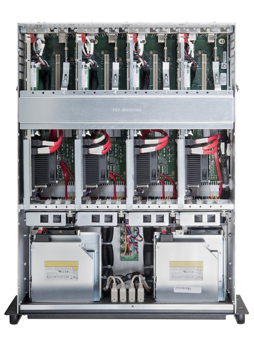
The airborne chassis shown in Figure 3 is made out of aluminum to further reduce system weight. Our Trenton Systems engineering team, in conjunction with the Tier 1 military OEM for this aircraft refresh program, developed redundant SBC hold-down brackets to ensure that the edge card fingers on the single board computers remain in place inside the backplane card slots during flight operations. This system illustrates how multiple PICMG 1.3 SBCs can be placed into a single computer enclosure to solve the problem of compute density.
The right form factor choice eases design challenges
There are a lot of single board computer form factors available for military and government computing applications. Sometimes a custom SBC design is required for the job and other times choosing a standard form factor from the plethora available today works just fine. The trick is to match the correct form factor to the application requirements, as far as compute density is concerned. Additionally, increasing processor capability generally means increases in heat generation. Fortunately, new processor die designs are mitigating this basic law of physics, but designers still need to do their system design homework to ensure a successful SBC implementation and to get the described SBC trends working in their favor.
Brad Trent is Director of Engineering for Trenton Systems. Brad has held various development engineering positions in the embedded computing, industrial automation, computer workstation, and process system control industries. He holds a BS in Nuclear Engineering from The Georgia Institute of Technology in Atlanta. Contact him at [email protected].
Trenton Systems 770-287-3100 www.TrentonSystems.com