Hardware full disk encryption technology for military applications using two-layer commercial solutions
StoryJanuary 19, 2018

Philip Fulmer
Mercury Systems
Bob Lazaravich
Mercury Systems
While the consumer market promotes rapid adoption of new microelectronics with ever-shortening product life cycles, the military market demands risk mitigation and long-term supply continuity - even for commercial-off-the-shelf (COTS) parts modified or screened to military requirements. Given the advantages of solid state drive (SSD) devices that consumers take for granted today, it is not surprising to see SSD devices adopted for military applications. In a prior publication, we defined the standards for a military grade data storage device with security designed in from the early stages of development. This new class of military storage devices, referred to as Secure SSD, is engineered with security built-in from the design phase.
Historically, classified, secret, and top-secret data storage could only be accomplished through the implementation of a government-off-the-shelf (GOTS) Type 1 security solution. Following government protocols, the desired end result – data-at-rest (DAR) protection – is achieved. Although the detailed steps required for practical implementation of a Type 1 security solution are beyond the scope of this article, Type 1 security solutions are broadly associated with lengthy implementation times and significant development costs. The integrity or suitability of a Type 1 security solution for data-at-rest protection is not questioned.
Recognizing that U.S. government customers have an increasing need for the most advanced and highly agile commercial technologies, the National Security Agency (NSA) and the Central Security Service (CSS) launched the Commercial Solutions for Classified (CSfC) Program. A key aspect of the CSfC program is the ability to deploy a security solution in months instead of years.
According to the NSA, “Instead of building government owned and operated solutions, whenever possible, NSA is moving to a defense-in-depth approach using properly configured, layered solutions to provide adequate protection of classified data for a variety of different capabilities.”
CSfC solution architectures
CSfC implementation requirements are defined by capability packages published by the NSA. As emphasized in the prior reference, each layer of security technology must be properly configured per the specifications outlined in the appropriate capability package. Four capability packages are available at the time of this writing; as this article focuses on hardware full disk encryption technology, only one capability package is discussed – Data-at-Rest (DAR).
The CSfC program simultaneously implements two or more independent commercial security components together to provide a layered security approach for the storage of classified data. Each of the security components, or layers, must be validated to CSfC requirements. The two security layers are referred to as the inner layer and the outer layer, as shown in Figure 1.
Figure 1: Two layered approach to securing sensitive data.
|
|
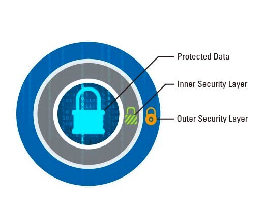
Both the inner and outer security layers must integrate Suite B encryption algorithms. In doing so, the security redundancy provided by the second layer of security renders it unlikely that an adversarial force could penetrate both security layers, provided that all CSfC requirements are successfully met. It is important to note that the CSfC program requires diversity when selecting security components.
At first glance, the diversity requirement may seem puzzling. The intention of redundant security components is to mitigate the risk of failure of any one particular component. However, a single vendor producing multiple security components may use similar, if not identical, design principles for each component’s cryptographic algorithm. If a security flaw in two separate components originates from the same fundamental design weakness, infiltration of one security layer quickly provides an adversary with a similar bypass through the second security layer. Maximum protection, and full compliance with CSfC program guidelines, can only be achieved with proven diversity in the selection of security components. It should be noted, however, that NSA documentation does permit a single vendor to produce multiple security components. This scenario requires definitive evidence and agreement from the NSA that each cryptographic algorithm was developed using distinct and independently developed resources and design methodologies.
Once a security component is validated and eligible for use as a CSfC security component per NSA guidelines, the manufacturer must enforce strict change control procedures. Failure to adhere to copy-exact manufacturing requirements may introduce security threats. For example, consider the scenario where the manufacturer of an ASIC [application-specific integrated circuit] controller introduces a minor change to the ASIC’s internal ROM [read-only memory] firmware but fails to notify its customers. In the course of implementing the manufacturing change, there is the potential for the integrity of the device to be compromised, intentionally or unintentionally. Suppose that such a change, for example, were to accidentally introduce a security bypass mechanism or activate a previously disabled key recovery procedure. A discontinuity in a trusted supply chain may have catastrophic effects far beyond the scope of the intended purpose.
Building CSfC data–at-rest solution
The Data-at-Rest capability package published by the NSA classifies security components into four categories, as discussed below. Conformance with CSfC requirements demands that two independent security components be selected while maintaining independence of cryptographic algorithms development. Two of the security components use full disk encryption (FDE) while the remaining two employ file or platform encryption.
- Software FDE (SWFDE): SWFDE components encrypt all data on the hard drive, including the computer’s operating system. The boot sequence and subsequent access to the data can is only permissible after successful authentication.
- File encryption (FE): FE encrypts individual files or sets of files in a device. Access to the encrypted data is only provided after authentication has succeeded. Encryption may be performed by an application, platform, or the host operating system.
- Platform encryption (PE): PE is provided by the operating system for platform-wide data encryption. PE differs from FE in that PE is only an inner layer and FE is only an outer layer. The primary technical difference between the two related to the hardware key protection requirements.
- Hardware FDE (HWFDE): HWFDE components use encryption algorithms embedded into the storage controller. An authentication key is used to decrypt the data encryption key (DEK) and provide access to the data. The primary subject of this article centers on the application of HWFDE technology.
Table 1: Data-at-rest solution designations for permissible inner and outer layer combinations.
|
|

Data-at-rest solution components are the fundamental building blocks required to develop, register, and provide maintenance for a CSfC registered solution. The NSA provides clear instructions for specific combinations of solution components to be integrated as inner and outer layers. Although theoretically 16 combinations are possible with four different security component types, only four solutions are authorized configurations. These four solutions are designated by two letter acronyms, where the first letter represents the inner layer and the second letter represents the outer layer. For example, the HS solution uses HWFDE as the inner layer of protection and SWFDE as the outer layer of security.
Selection of the appropriate solution – SF, PF, HF, or HS – should be done only after careful consideration of the application and its security requirements. For clarity, the authors do not endorse any single solution design. Readers are encouraged to carefully evaluate the DAR Capability Packages to identify the most appropriate solution designation for their specific security application.
HWFDE component considerations: security
Having completed a discussion of the CSfC program for those unfamiliar with the program’s requirements, consideration can now be given to the integration of a Secure SSD into a two-layer CSfC solution as a HWFDE inner layer component. Per CSfC program requirements, the outer layer component must be either FE or SWFDE. Before continuing, it is important to note that there is no single universally superior HWFDE component for every security implementation. Readers are encouraged to reference NSA documentation to determine the most appropriate solution implementation for their specific security implementation.
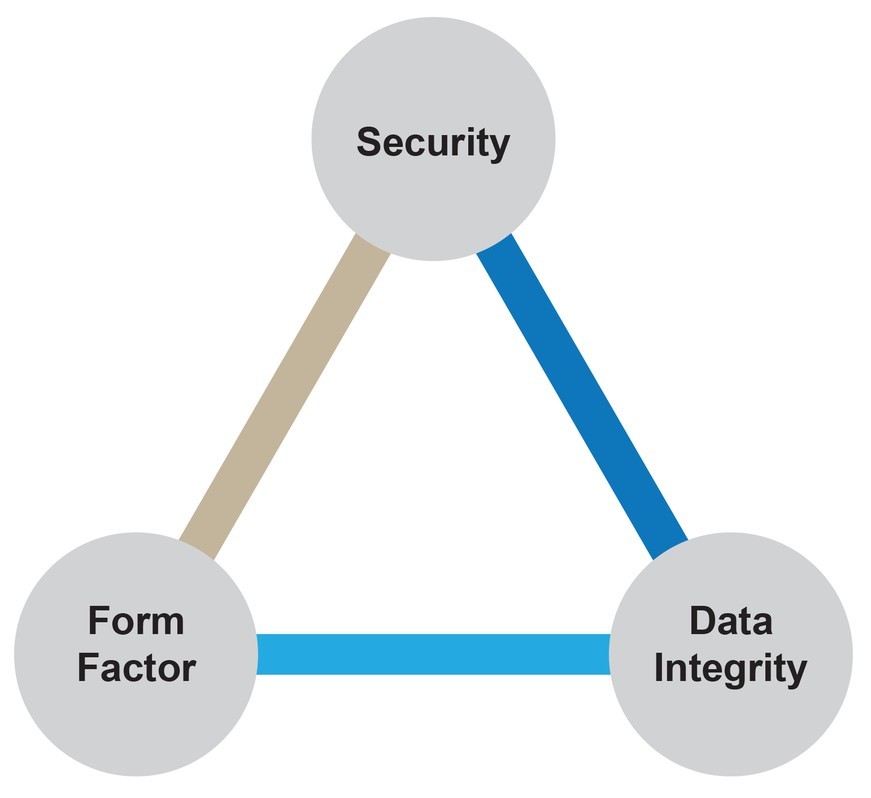
Figure 2: HWFDE Component considerations: Security, data integrity, and form factor.
|
|
HWFDE components may be either a conventional hard disk drive (HDD) with rotating magnetic media or a solid-state drive (SSD) using NAND flash storage media. Given the reliability and performance differentials between SSDs and HDDs, most applications today select solid-state technology for data storage. Both configurations require self-encryption functionality, which is typically achieved through implementing cryptographic algorithms in the drive’s controller and/or processor.
Careful selection of HWFDE components must be made to ensure that the cryptographic algorithm deployed in the inner HWFDE layer is distinct from the selected outer security layer, either FE or SWFDE. Authentication of the HWFDE component can be performed using a randomly generated passphrase or a randomly generated bit-string equivalent to the cryptographic strength of the DEK. Passphrases must comply with requirements outlined in the DAR capability package, most notably the minimum strength calculations.
There are additional considerations. Data must be protected with the strength of advanced encryption standard (AES) with 256-bit keys and an XTS (XEX with ciphertext stealing), GCM (Galois/Counter Mode), or CBC (Cipher Block Chaining) block cipher mode. Generally, XTS implementations are preferable. In doing so, all classified data must be encrypted on the device without exception.
Additionally, the encryption key for each layer must be distinct. If an adversary were to gain access to one of the encryption keys, unique encryption keys for each layer prevents access to the encrypted data. In the event that the encryption key is purged from the device, there must be no remnants of the key on the device and there must be no way to recover the key from the drive.
HWFDE component considerations: Data integrity
The discussion above highlights the multitude of considerations that must be addressed before a storage device can be deployed in a CSfC solution. The same degree of scrutiny should be applied not only to the security of the data but also to any device consideration that impacts the integrity of the data. Any data, classified or unclassified, may be highly valuable and irreplaceable for a military operation. The malfunction of a device during a mission may have disastrous consequences. In the following discussion, let us discuss considerations for a user when selecting one HWFDE component over another.
First, the NAND flash media type must be matched to the performance demands of the application and its environment. NAND flash manufacturers now offer a myriad of technologies available to the consumer:
- Single-level cell (SLC) NAND flash stores only 1 bit per cell yet offers 10X higher data endurance than the next best alternative media type. It also has the most robust operating temperature range, –40 °C to +85 °C. SLC technology is the media of choice for applications storing data that cannot be replaced in the event of an SSD failure.
- Multi-level cell (MLC) NAND flash, in contrast, stores 2 bits per cell, thereby offering a larger data storage capacity at a significantly reduced cost. However, this increased capacity comes at the expense of reduced read/write endurance compared to SLC NAND and shorter data retention.
- Triple-level cell (TLC) technology stores three bits per cell, thereby further reducing cost, with additional penalties beyond MLC technology in terms of data endurance and operational lifetime.
- 3D-NAND technology vertically stacks storage cells to surmount the scaling limitations of conventional planar (SLC, MLC, TLC) technologies. At the time of this writing, 3D NAND memories are available only with operating temperatures of 0 to +70 °C. Although 3D-NAND technology does allow further scaling, the vertical integration does present new reliability issues.
With a myriad of NAND technologies, selecting the appropriate SSD for a given application is not a trivial exercise. As a rule of thumb, selecting a SSD based on SLC technology is clearly the safest approach when data integrity is critical and/or operating temperatures are below 0 °C or exceed 70 °C. Under commercial operating temperatures where the SSD can be readily replaced as a preventative maintenance operation, MLC technology offers higher storage capacities suitable for high-volume data record recording applications where the data has limited lifetime value. At the time of this writing, TLC and 3D NAND technologies have not yet reached a maturity level where the authors can recommend their consideration for military applications.
Those selecting a HWFDE component are encouraged to inquire with the manufacturer about performance throttling algorithms designed to extend the useful lifetime of a device. Normally these algorithms are activated under heavy duty-cycle operation or high temperature operation, but are not advertised by the SSD manufacturer. Extended operational lifetimes sounds like a benefit to the user; however, extended operational lifetime comes at the expense of non-deterministic and reduced read and write speeds. Although potentially acceptable for commercial applications, many military applications demand continuous high-speed data capture at extended temperatures for a successful mission.
Assuming the NAND flash media and controller architecture of the SSD have been addressed, one additional question remains: In the event of a sudden power loss, what happens to the cells that are being read and/or written? A sudden disruption in power may lead to the corruption or loss of data if the device has no mechanism to ensure an orderly and deterministic shutdown procedure. Batteries, supercapacitors, and other means of data preservation can be integrated into the device’s architecture. Users are cautioned when selecting any solution deploying batteries or supercapacitors, as their effectiveness is limited in environments requiring low and high temperature operation.
HWFDE component considerations: Form factor
The industry standard 2.5” form factor is the defacto configuration. However, not all 2.5” SSD packages are created equal. The shock and vibration conditions, both expected and unexpected during deployment, must be evaluated. The physical package/enclosure of the SSD must be structurally validated to survive all shock and vibration conditions possible in the given application. Further consideration must be given to the integrity of the mechanically connecting interface between the SSD and the host system. Ruggedized mechanically interlocking connectors minimize the possibility of an accidental disconnect from the host system. Scenarios may arise where a user requires an alternate form factor, such as mSATA or XMC card.
Can the SSD manufacturer support the rapid development and qualification procedures to achieve eligibility for use as a CSfC solution component? Is the controller architecture portable and readily adapted to the new form factor? If the manufacturer has not even achieved third party qualifications -- such as FIPS 140-2 and Common Criteria -- on one form factor, it is highly unlikely that the review and qualification process needed for the new form factor can be completed quickly.
A properly configured and implemented two-layer security solution per CSfC program guidelines can be used to properly secure sensitive military data. For security implementations using hardware full disk encryption technology, however, not all hardware solutions are created equally. Careful consideration must be given to the use case scenario. In particular, the hardware manufacturer’s choice of design parameters, which are not specified by the CSfC program, may have both short- and long-term consequences for the security implementation.
Bob Lazaravich is the Technical Director for the Secure Solid State Drive product line at Mercury Systems in Phoenix, Arizona. Bob frequently engages with customers to implement security features tailored to address application-specific requirements. Bob received his BSE and MSE degrees in Electrical Engineering from Arizona State University. Philip Fulmer is the Director of Product Marketing for the Advanced Microelectronics Solutions group in San Jose, California. Philip received his BS degree in Chemistry from the University of Scranton and MSE degree in Materials Science and Engineering from the University of Texas at Austin.
Mercury Systems • www.mrcy.com