Designing rugged, multifunctional HPA controllers to prevent system damage
StorySeptember 02, 2011

Mario Razo
dB Control
Meppalli Shandas
dB Control

High Power Amplifiers (HPAs) are critical in microwave systems commonly found in Electronic Countermeasures (ECM), Electronic Warfare (EW) simulators, radar, and communications links used by the military. Unfortunately, integral Vacuum Electron Device (VED) requirements introduce hostile environments for HPAs. However, a rugged, multifunctional, microcontroller FPGA-based controller can solve this challenge.
High Power Amplifiers (HPAs) are the backbone of most microwave systems used for military applications such as radar, Electronic Countermeasures (ECM), communication systems, and Electronic Warfare (EW) simulators. HPAs using Traveling Wave Tubes (TWTs) come in two categories. Both versions use Vacuum Electron Devices (VEDs), TWTs, Klystrons, and Gyrotrons to amplify the modulated RF waveforms given at the input to the desired power level before feeding to the radiating element.
The difference is that one version of the HPA is the microwave power amplifier with all RF input and output parts, power amplifying TWT (or other VEDs), digital interface and protection circuits, and the power supply all integrated into one assembly. The other version is the compact Microwave Power Module (MPM), which uses a miniature version of the TWT and a solid-state driver amplifier integrated with a densely packaged power supply (Sidebar 1). Being a very compact module, the MPM does not have all functions within the assembly and can produce RF power in the range of about 100 W CW or 1,000 W peak pulse power. The VEDs require high operating voltages of 5 to 25 kVdc and proper switching sequences and protection circuits.
Sidebar 1: An inside look: How microwave systems solve high-power electronic attacks
(Click graphic to zoom)
|
|

To keep the HPA controller functioning is vital for continued effective systems operation. Thus, to prevent damage to costly parts and the system, ongoing monitoring and status indication of every critical parameter are essential. For example, HPA controllers must monitor HPA health by measuring critical parameters such as the cathode voltage, current, body temperature, and so on. Controllers must also provide protection to prevent damage, in addition to offering interface between the HPA and host system, executing housekeeping functions, and functioning as the Built-In Test (BIT) system for the HPA.
In addition, HPA controllers must be able to withstand a “hostile” environment, as they reside in an area of the system where they can be subjected to high voltages up to 25 kVdc, high-energy switching up to 10 Joules, and other severe operational stresses such as extreme temperatures (-55 °C to +125 °C) and high vibration levels of up to 20 G rms. This is further complicated by the high levels of switching currents in the order of 100 A per microsecond and short-circuit currents of thousands of Amps. If such currents were to be going through any of the VEDs, it will destroy these expensive devices beyond repair.
The design challenge is to provide suitable protection and integrate BIT functionality and continuous monitoring into a microcontroller FPGA-based embedded controller because of the HPA’s “hostile” environment. Design engineers must consider the “hostile” environment factors prior to establishing the appropriate architecture for HPA embedded controllers. Figure 1 illustrates a basic HPA system architecture. Three major modules form an HPA system: a VED, a controller, and a high-voltage power supply that provides the required voltages to different elements of the VED such as the heater, cathode, collectors, and the electron beam. The HPA controller offers control and protection for the entire system.
Figure 1: The basic HPA system includes a VED, power supply, and HPA controller.
(Click graphic to zoom by 1.9x)
|
|

Protecting HPA systems’ critical components
Every HPA system requires control and protection circuitry to protect the VED and other critical system components from adverse conditions and possible failures that could lead to major system damage and considerable economic impact. There are several factors to consider when designing high-performance HPA embedded controllers. For example, the high operating voltages (5-25 kVdc) required by an HPA system can cause severe damage to sensitive components such as microprocessors, microcontrollers, FPGAs, memory devices, Analog-to-Digital Converters (ADCs), and other critical components. Extreme protection is required to keep these devices safe and active under any circumstance, especially when high voltage and switching current spikes occur. Current spikes of HPA systems can vary from a few Amps peak up to hundreds of Amps peak, depending on the VEDs’ requirements.
The hostile environment surrounding the embedded controller can also cause false alarm failures or unexpected behavior. Switching noise produced by the power supply switchers can produce extremely sharp noise spikes of nanoseconds duration, which can occupy more than a few MHz of bandwidth. These can corrupt critical signals of the HPA system such as Serial Peripheral Interface (SPI), Inter-Integrated Circuit (I2C), and serial data lines.
The HPAs need to meet various conditions such as time delay required by VEDs (180 seconds typical), operate command from the host interface, and Focus Electrode (FE)/grid enable and beam control (-1100 Vdc to +500 Vdc) prior to amplifying any given RF input signal of 2 to 40 GHz. The HPA controller must keep control over these signals and execute the commands in the right sequence under any condition to assure safety and proper functionality of the HPA system. Improper switching sequence of these signals could damage the VEDs, accidentally transmit RF output power (in some cases 10 kW peak), or harm personnel. Implementation of control signals with safe-state configuration is necessary to achieve a suitable and safe HPA controller. Safe-state signals will protect the VEDs from being active during initial power-up, standby, or when transmission is not desired. The integration of microcontrollers and FPGAs into HPA controllers empowers HPA systems by providing high-performance protection and extensive functionality, as will be discussed later.
“Universal” controllers satisfy next-gen systems
Modern mission-critical systems require HPAs that meet all performance requirements, provide 100 percent availability for the mission duration, and act as multifunctional HPA controllers capable of withstanding high-stress environments while effectively performing essential functions. A high-performance “universal” HPA embedded controller with an input power of +15 Vdc, 5 W, and dimensions of 6.0" x 2.5" x 0.90" can meet these requirements for next-generation military airborne systems. Figure 2 depicts its basic block diagram and hardware architecture.
Figure 2: Multifunctional embedded HPA controller powered by an FPGA and a microcontroller
(Click graphic to zoom by 1.9x)
|
|
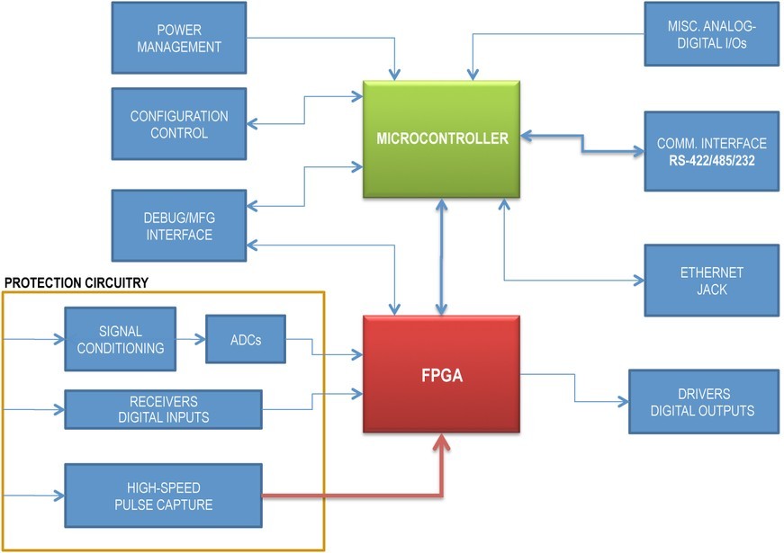
The main function of this embedded HPA controller is to protect the critical elements of the system by monitoring the diverse parameters of VEDs such as Helix current up to 600 mA, cathode voltage from 5 kV to 25 kV, over-temperature (typical 125 ºC), and output reflective power up to 100 W average. These parameters vary from VED to VED, and the embedded controller offers flexible protection limits. It also monitors other critical parameters of the HPA such as input current, input voltage, and temperature of the high-voltage power supply. Additionally, the controller provides built-in test features through different serial communication protocols such as RS-422, RS-485, or RS-232. This function enables the host interface to continuously retrieve (automatically or upon request) the HPA system’s status. The HPA controller provides status between 1 and 2 seconds after application of power.
The embedded HPA controller can receive commands such as Model Identification Query, Status Query, Operate, and Stand-by, for example, from the host interface via the serial interface and execute these commands almost immediately (in less than 20 ms) after reception and acknowledgement.
Using a microcontroller, FPGA to protect the HPA
The microcontroller and FPGA components are the main core of the embedded HPA controller that protects the EW, ECM, radar, or other military system electronics from damage; these controllers perform the majority of the tasks with aid from the protection circuitry section and other miscellaneous devices, as follows:
- The main functions of the microcontroller are overall supervision, host communication, self-test, and technician assistance features via RS-232. The microcontroller also verifies board/system configuration, communication with a remote panel, and communication with other controllers, and conducts periodic verification of FPGA configuration to guard against single-event troubles.
- The protection circuitry continuously monitors the HPA system’s critical parameters by collecting feedback from various HPA elements. Such feedback could be temperature readings (-55 °C to 150 °C), cathode voltage, helix current, reflected output power from the VED, input under-voltage, and more. The input gate signal (pulse systems only) is detected by a pulse measurement function inside the FPGA to protect the VED from over-duty of 3 to 30 percent, over-pulse width of 2 µs to 300µs, and over-frequency of 200 Hz to 100 KHz. The protection circuitry also incorporates a high-speed pulse capture that accepts RF detector signals. These signals are conditioned, scaled, and digitalized, and the FPGA transmits the digitalized values through the serial interface.
The FPGA enhances the HPA controller by providing an extensive set of features to make it more robust and multifunctional. The FPGA architecture includes configurable functions via tailored logic loads, polarity, and mask registers to allow a common logic load for multiple HPA systems.
The FPGA provides control of a 12-bit ADC and compares configurable thresholds against digitized voltage inputs such as cathode voltage (scaled down from 5-25 kV to less than 10 Vdc) and detected RF output power (-80mV) from the VEDs (typically amplified and inverted from -80 mV to +10 Vdc). Additionally, the FPGA captures and analyzes digitized data, performs gate-pulse measurements (2-300 µs with frequencies up to 100 KHz), and provides voltage-to-power conversion using a lookup table, in addition to peak detection.
As a safety feature, the FPGA is configured to keep the I/O signals in safe-state; the microcontroller is capable of detecting any FPGA malfunction on the next polling cycle and taking appropriate action.
HPA controllers for today’s military systems
While HPAs are essential in most microwave systems used for military applications such as ECM, radar, communication, and Electronic Warfare simulators, it can be challenging to integrate the necessary protective functions into the HPA’s embedded controller. The hostile environment introduced by HPA systems because of the VED’s requirements is inevitable, and it compromises the integrity of HPA embedded controllers. Design engineers are obligated to live with this matter and must protect the embedded controller. dB Control has developed such an embedded HPA controller, which is microcontroller FPGA-based, noise immune, multifunctional, and firmware configurable, minimizing the need for design changes and harnessing FPGAs’ and microcontrollers’ high performance and extensive functionality to protect the system.
Mario Razo is a Design Engineer at dB Control, working with high-power amplifiers and microwave power modules for military and commercial customers. Email him at [email protected].
Meppalli Shandas is dB Control’s VP of Technology and Business Development. He has 40 years of design experience with microwave hardware for Electronic Warfare, radar, and communication systems. Email him at [email protected].
dB Control 510-656-2325 www.dBControl.com