Lead-free rising
StoryJune 13, 2013

Ivan Straznicky
Curtiss-Wright

As Lead-Free (LF) electronics continue to supplant Tin-Lead (TL) alternatives, new research shows LF devices can match or exceed the reliability of TL components with proper mitigation techniques.
The use of Lead-Free (LF) components in commercial electronics, driven in large part by the European Union’s Restriction of the use of certain Hazardous Substances (RoHS) and Waste Electrical and Electronic Equipment (WEEE) directives that ban the use of lead and five other substances in many electronics applications, is of great interest and concern to designers of COTS-based modules and systems for the Aerospace and Defense (A&D) markets. As LF component use expands, it will become more difficult to obtain Tin-Lead (TL)-based devices. This issue is especially urgent for COTS products designed for use in harsh environments.
As LF devices replace TL alternatives, the LF components will increasingly form the foundation of advanced technology military applications. The reliability risks introduced by the use of LF devices must be carefully investigated, understood, and addressed. The good news is that the results of recent tests and research show that there are effective mitigation approaches today to address the leading risk concerns associated with the use of LF parts, and even better, that the reliability of LF devices can in fact match and even exceed that of TL parts. This new test data can help speed the adoption of LF while reassuring COTS customers that their risk is being reduced without compromising their application’s performance.
In recent years, as component manufacturers have increased the production of LF devices and the availability of TL parts has substantially decreased, leading COTS vendors, individually and in concert with related consortia, have undertaken deep research into the behaviors of LF components and assemblies. Such LF behavior was measured while assemblies were subjected to the harsh environments that rugged embedded products using these devices frequently endure (see Figure 1). The intense level of scrutiny and scientific research applied to the physics of failure of LF has resulted in some recent discoveries, both surprising and counterintuitive, that strongly suggest that in the near future the reliability of LF assemblies might actually outpace that of TL assemblies. One example is the discovery that small LF solder joints are often significantly more reliable in thermal cycling than larger LF solder joints. This bodes well for the COTS world as it aligns perfectly with the continued trend for higher-density, smaller interconnect microelectronic components over the foreseeable future, when tough design choices have to be made.
Figure 1: Lead-free assemblies in thermal cycling chamber
(Click graphic to zoom by 1.3x)
|
|

Concerns about lead-free
The Pb-Free Electronics Risk Management (PERM) Consortium’s Lead-Free Electronics Manhattan Project (LFEMP) reports identified two of the most important risk factors associated with LF as tin whiskers and pad cratering.
Tin whiskers
For most A&D customers, the biggest concern about LF devices has been the proliferation of tin whisker risk. (See this article’s lead-in photo of tin whiskers growing on a tin-plated copper leadframe, opposite page.) Over the years there has been much work done to characterize and address this phenomenon. A specification has emerged, the GEIA-STD-0005-2 Standard for Mitigating the Effects of Tin Whiskers in Aerospace and High Performance Electronic Systems. Recently revised, this standard identifies Conformal Coating (CC) as the main mitigation technique of choice to combat tin whiskers. And while many different CC materials are available, not all have the same level of efficacy. Parylene, which uses a vapor deposition process, is a leading approach to prevent tin whiskers from forming or to slow down their growth on a particular surface. In the case that a tin whisker should penetrate the coating, parylene is also effective in preventing an electrical short to an adjacent circuit. Additionally, test data has shown that parylene actually strengthens solder joint reliability. While parylene usage is sometimes encouraged, two alternative materials, acrylic and urethane, can also be used on a program-by-program basis when appropriate.
Pad cratering
Another large concern associated with the introduction of LF is pad cratering (see Figure 2). This phenomenon is an insidious failure mode that can easily escape detection and can be an issue with both LF and TL assemblies. The main culprit in pad cratering is the brittleness of many new PWB materials. The problem is mechanical in origin and tends to occur most often when the PWB is bent, during instances of high vibration, for example, or from BGA package warping. Mitigating pad cratering involves making changes to the pad geometry in select locations such as the corners of the BGA. Making changes in the type of PWB laminate, such as selecting materials with greater ductility, can also be helpful in mitigating the problem.
Figure 2: Pad cratering on memory device
(Click graphic to zoom by 1.9x)
|
|

Stronger, smaller solder joints
The increased amount of research into the behavior of LF devices has also shown that small LF solder joints can last significantly longer than larger solder joints (see Figure 3). This surprising result is the complete reversal of what is found with TL components. With lead-based devices, a BGA with a fairly high standoff is more reliable than a BGA with smaller solder joints and a lower standoff. This knowledge drives the popular use of solder columns to improve solder joint reliability for leaded components. Counterintuitively, new materials science research into LF parts/assemblies shows instead that small solder joint sizes – on the order of 100 microns or less – produce a different and beneficial solder microstructure (see Figure 4) that provides significantly greater reliability for LF devices than that found in solder joints larger than ~100 microns. As electronic devices continue to get denser, the trend toward miniaturization is likewise making solder ball pitches much more dense. The higher reliability of smaller solder joints that comes with LF components aligns well for future design trends in A&D system design.
Figure 3: Thermal cycling results of different sized lead-free solder joints (Courtesy: Universal Instruments)
(Click graphic to zoom by 1.9x)
|
|
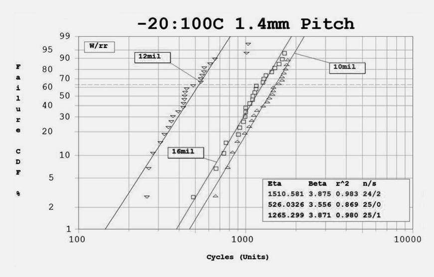
Figure 4: Small lead-free solder ball with beneficial microstructure (Courtesy: Universal Instruments)
(Click graphic to zoom)
|
|

Choosing lead vs. lead-free options
Each designer has to make decisions about how and when to proceed with LF components. Today, there are three main options available to COTS vendors when deciding to adopt or avoid use of lead-free components:
- Reball area array components to tin-lead, and solder with tin-lead solder.
- Accept lead-free components and solder with lead-free solder (predominantly SAC305).
- Take lead-free components and solder with tin-lead solder.
When done properly, the first approach essentially brings electronic assemblies to the baseline solder joint reliability of TL. This approach does not eliminate concerns about tin whiskers and, possibly, printed circuit boards, but further mitigations can be put in place such as solder dipping of non-BGA components and/or conformal coating. Reliability concerns also arise because of additional heat exposure and handling required for component reprocessing, although these can be mitigated through appropriate process controls. The direct costs associated with this approach are likely to be the highest of all three scenarios.
We now know that LF devices soldered with LF solder can be as reliable, or more reliable, than reballed LF parts soldered with TL. Results from recent testing that compared the reliability of LF BGAs soldered with LF solder with the performance of reballed BGAs soldered with SnPb, show that while both LF and TL typically deliver acceptable reliability, in virtually all cases, the LF/LF BGA outperformed the reballed TL configuration. Another surprising result in favor of LF is that thermal aging did not degrade the reliability of LF devices to less than that of TL devices; in fact, thermal aging improved the reliability of LF devices relative to TL-based parts. This is also good news because of the high cost in both time and money that reballing LF devices incurs.
The second approach, using LF devices with LF solder, is being used worldwide in other industries, and has been favored by some in the COTS industry because of lower direct costs and reduced lead-time impact. However, reliability risks remain with this approach and the burden of reliability proof will lie with the customer unless the supplier can show how they have addressed reliability risks and knowledge gaps. There is a large amount of data available for some aspects of this approach (for example, thermal cycling), but the details need to be assessed as to applicability to a manufacturer’s products. Curtiss-Wright endeavors to be at the forefront of producing LF test data in A&D environments (for example, extended temperature cycling, vibration) on representative COTS components and assemblies, and comparing these to tin-lead and mixed solder approaches.
The third option available to COTS product designers is the mixed solder approach. In this tactic, area array components (for example, BGAs) with LF solder balls are soldered with TL solder. This approach is an attempt to get the best of both worlds in terms of lower costs and lead-time impact (no time-consuming component reprocessing required) and less perceived risk (TL solder). Once again, the burden of reliability proof lies with the customer unless the supplier can convince them otherwise. While some studies have shown that this approach might result in acceptable thermal cycling reliability when using commercial temperature ranges, others have shown inconsistent reliability across several component packages using an extended temperature range. Overall, the details of this approach (for example, solder microstructure, strength, fatigue, and acceleration factors) are less understood than the LF approach.
Today, it appears that the first of the three approaches (reprocess to TL) is favored by the majority of A&D system integrators and prime contractors. However, the continuing drive to lower costs in A&D makes this approach less attractive. The second and third approaches involve lower direct cost, but until recently (for option 2), reliability has been a question mark for A&D customers.
Lead-free today
Recent research indicates that the reliability of LF components/assemblies can match and exceed that of leaded devices. The results so far suggest that TL-based components might soon become a thing of the past without reducing the reliability or performance of critical A&D embedded systems. Additionally, Curtiss-Wright continues to produce legacy products with lead-based components, and though we do not foreclose the possibility of designing new products using lead components, today most of our new products are lead-free designs. Recently derived extensive test data and industry experience have thus enabled the necessary “secret sauce” to develop mitigation techniques that ensure the successful use of LF components in the harshest military environments.
Ivan Straznicky is a Technical Fellow at Curtiss-Wright Controls Defense Solutions. He received his Bachelor of Mechanical Engineering from McGill University and is a Certified Advanced Technology Manager. His responsibilities include advanced thermal and packaging technologies. Ivan has more than 20 years of experience in the military/aerospace industry in manufacturing and mechanical engineering and management. He frequently contributes to the industry’s publications and conferences through technical articles and presentations. Contact him at [email protected].
Curtiss-Wright Controls Defense Solutions 613-599-9199 www.cwcdefense.com