Creating a simulated environment for UAS operator training
StoryOctober 27, 2009

Yannick Lefebvre
Presagis
The military's increased worldwide use of Unmanned Aerial Systems (UASs) is driving the demand for highly realistic training environments. Using a mix of integrated 2D and 3D COTS graphics tools can greatly accelerate the development and realism of simulators to fulfill this growing need.
Unmanned Aerial Systems (UASs) are increasingly being used by military forces around the world. Whether for reconnaissance work or tactical engagements, unmanned vehicles are remotely controlled from a ground station and provide extraordinary capabilities in range and agility while eliminating risk to human life. To execute tasks, operators need to be trained in a variety of skills, from the interpretation of visual information that the UAS provides to reacting correctly based on the situation at hand.
Simulating a UAS ground station is complex and requires many different technologies to work together to produce the final result for trainees. When creating a simulated environment for operator training, critical elements such as the UAS’s sensor output and graphical overlays that display data used to pilot or control the vehicle need to be delivered in an intuitive way to ensure an effective training environment is provided.
From a system design perspective, it may be easier to simulate sensor outputs and graphical overlays on several different screens using disparate technologies. From a trainee’s perspective, this approach can create unnecessary workload and the significance of an overlay’s exact positioning over the UAS’s sensor feed could be lost. The optimal solution is to merge both the UASs sensor feed and its visual overlays into a single screen using a Commercial Off-the-Shelf (COTS) 3D image generator with a COTS 2D human-machine interface modeling tool to ease the process of merging these applications and provide a more effective and intuitive UAS training system (Figure 1).
Figure 1: A simulated 3D camera view with 2D static and interactive graphical overlays.
(Click graphic to zoom by 1.2x)
|
|

Matching requirements with technology
COTS 3D image generation systems are available to simulate UAS sensor feeds. This type of application can render synthetic animated environments on-screen such as terrain, buildings, moving vehicles, atmospheric effects, and any other details that make a virtual world come to life. Beyond receiving continual product updates over the lifespan of a project and benefiting from a proven framework, opting for a COTS image generator brings additional functionality that elevates the realism of a UAS ground station simulator such as simulating high-fidelity sensors (night vision goggles and infrared, for example). In contrast, developing such advanced visual features in-house is cost-prohibitive, time-consuming, and quite challenging as it requires a very specific expertise.
For the 2D overlays that are presented to the operators on top of the sensor feed, such as a Heads-Up Display (HUD) or a targeting reticule, a COTS Human-Machine-Interface (HMI) design software is best suited as it enables developers to visually define the elements of the overlay along with their respective functionality, data ranges, and information sources without needing to write code manually. Once a design is finalized, an automatic code generator packages the display contents as a self-contained executable program. Using a COTS HMI design software for this part of the development introduces advanced authoring concepts such as graphical logic creation and accelerates the development cycle by using a graphical user interface instead of manual coding.
Integrating 2D and 3D graphics
Once the 2D overlays and 3D graphics have been developed, they need to be integrated into one cohesive method to provide the trainee an integrated view that accurately represents the real-life equipment.
For this to be possible, both the 2D HMI design software and the 3D image generator need to use the same graphical language to draw graphics on-screen. If they don’t, it will be difficult – if not impossible – to integrate them within the same environment. In today’s desktop and embedded computing world, the graphical language of choice is usually OpenGL.
Another concern that needs addressing is that the graphics code produced by the HMI design software needs to adapt itself to being rendered in a larger environment and not clear the screen buffer when it renders its graphics so that the underlying 3D graphics don’t get erased.
One last consideration before starting the integration of these two technologies is the authoring of the 2D overlay graphics. Since they will be rendered on top of the 3D environment with transparent elements, graphical techniques such as masking (using visual elements that are the same color as the background as masks) should be avoided as they would produce undesirable visual artifacts.
There are two common approaches that can be followed to perform this integration. The first and more manual method is to take the generated code from the HMI design tool and call it from a post-draw function within the 3D image generator. A post-draw function is a programming hook that allows users to render their own graphics once the 3D virtual world has been completely displayed. This integration technique requires skilled programmers who are familiar with both technologies at hand.
An easier approach that is provided through the use of COTS HMI design software is to encapsulate the 2D graphical overlay as a Dynamic Link Library (DLL) plug-in with a defined communications interface and to load the resulting component in a COTS 3D environment that supports external plug-ins and offers a visual configuration utility. In addition to simplifying the integration of the visual overlays with the UAS sensor feed simulation, this technique makes it easy to iterate through the development of an application by only having to generate a new plug-in file after making changes to the overlay graphics.
Figure 2: 3D rendering pipeline with 2D overlay integration.
|
|
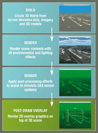
Once the display code is loaded in the 3D display, it needs to be animated. Most often, this is done by sending data to the 2D overlay using a communications structure that is defined in the HMI design. Once data is assigned to the interface, the display elements that are linked to incoming variables automatically update themselves to reflect new values. Figure 2 depicts the 3D rendering pipeline with 2D overlay integration.
In terms of data transport mechanisms, information can be sent by using API functions defined in the DLL plug-in or through direct communication between the overlay code and external data sources. The first method would be used if data displayed by the overlay is shared with the 3D scene (for example, pitch, roll, and altitude). The second technique is used in situations where the overlay data is hosted outside the visual system (for example, targeting reticule or engine data) and needs to be transported over protocols such as UDP, TCP, or shared memory.
The benefits of an integrated solution
The use and integration of COTS 2D and 3D graphics is the best way to create an environment that is closest to the real equipment that trainees need to become familiar with in a UAS ground control station. The need for dynamic, intuitive and realistic training environments continues to increase in tandem with the growth of the UAS market. Developers play a key role in the creation of accurate and immersive training programs and must understand how COTS technologies such as HMI design software and a 3D image generating system help them deliver high-quality simulators efficiently. By eliminating the need for hand-coding and using tools that offer advanced logic authoring and the ability to easily integrate 2D and 3D, developers will stay one step ahead of the market curve.
Yannick Lefebvre is a senior application developer at Presagis. With a background in computer sciences and 12 years of experience in modeling and simulation, Yannick has provided counsel on hundreds of simulation and embedded display programs globally and is considered an expert in the industry. He can be reached at [email protected].
Presagis 514-341-3874 www.presagis.com