Switches and routers: The difference is critical
StoryOctober 10, 2013

Shane Murray
Curtiss-Wright
Today’s ground combat vehicles are being outfitted with an increasing number of onboard electronic subsystems, all of which want to be interconnected via the platform’s local Ethernet network.
Today’s ground combat vehicles are being outfitted with an increasing number of onboard electronic subsystems, all of which want to be interconnected via the platform’s local Ethernet network. The problem is that as more and more network traffic gets generated between these subsystems, the threat of network congestion increases, resulting in unacceptable performance degradation and slowing the transmission of critical data to the destination(s) that most need it as quickly as possible. Worse, if only a Layer 2 switch is used for directing network traffic instead of a Layer 3 router, the users will lose the ability to apply network management controls that help eliminate the threat of network congestion and provide security rules that prevent network traffic from reaching off-limits network nodes.
It’s simple: A switch is not a router
All too frequently, the only approach taken to support a large network of subsystems in a ground vehicle platform is a Level 2 switch, not unlike what you might purchase inexpensively from a big-box electronics store and utilize in your small home network. Simplicity and low cost make switches attractive, but it’s important to understand the price your ground vehicle network might have to pay because of a lack of understanding of the critical feature and performance limits that Layer 2 switches bring compared to Layer 3 routers.
The OSI’s seven-layer network model defines Layer 1 as the physical layer that defines the physical transmission media used to connect devices to the network. This includes the electrical connection (for example, copper wire or optical cable) and a protocol to terminate the connection of directly connected devices.
Layer 2, the data link layer, is defined as a reliable link between two directly connected nodes that detects/corrects errors that arise in the physical layer. Layer 2 switches enable multiple data links to be interconnected, but provide no controls and are unable to set priorities for data. Because Layer 2 switches treat all data equally, the result can be congestion and delayed transmission of the most important data.
Layer 3 is defined as the network layer, and provides layer-management protocols, such as routing protocols, multicast group management, network-layer information and error, and network-layer address assignment. A Layer 3 router can control which user gets what data. Even better, Layer 3 routers support Access Control Lists (ACLs) and filters that optimize bandwidth and cure network congestion. Layer 3 routers also support inter-VLAN routing.
Access Control Lists (ACLs)
One of the important advantages that Layer 3 routers have over Layer 2 switches is their support for the use of ACLs. ACLs enable network designers to establish and manage security rules; for example, to permit or deny the transmission of specific Ethernet packets. Using ACLs, the network administrator can define a network security criterion that limits certain types of data from reaching sensitive destinations.
Inter-VLAN communication
Many networks require VLANs to separate equipment traffic for broadcast messaging, but still require communication to the entire network for management of the overall system. Achieving this with a switch would require an external router to connect these VLANs. Utilizing a Layer 3 router to perform both the VLAN segmentation and inter-VLAN routing optimizes the Size, Weight, and Power (SWaP) in modern combat vehicles.
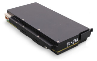
Figure 1: Curtiss-Wright’s SwitchBox SMS-684 supports 24x 10/100/1000 MBps interfaces and 4x 10 GbE-SR fiber-optic ports in a rugged compact chassis.
(Click graphic to zoom by 1.8x)
|
|

An example of a compact, stand-alone network interconnected subsystem that provides both Level 2 switching and Level 3 routing is Curtiss-Wright’s SwitchBox SMS-684 (see Figure 1). It supports 24x 10/100/1000 MBps interfaces and 4x 10 Gigabit Ethernet (GbE)-SR fiber-optic Ethernet ports in a rugged stand-alone chassis. All GbE ports are available through MIL-C-38999 connectors. This Ethernet switch is fully qualified for rugged applications with no active cooling components required and is qualified for reliable operating in harsh environments. All of the 1 GbE ports support full auto-negotiation and auto-MDI/MDIX crossover to simplify integration. Further, the switching core provides a full-speed, non-blocking architecture for full wire-speed performance on all ports.
Shane Murray Product Marketing Manager Curtiss-Wright Controls Defense Solutions www.cwcdefense.com