Meeting the needs of millimeter-wave 5G small cells for defense and beyond
StoryDecember 01, 2022

Alexander Ippich
Isola Group

Fifth-generation networks, known as 5G, offer extensive wireless services with even faster data rates to come for such uses as military and mission-critical communications, enhanced mobile broadband, and the massive Internet of Things (IoT). Most of the systems to date have been based on signals below 6 GHz. Once network coverage has been achieved at higher millimeter-wave (mmWave) frequencies of 24 GHz and higher, 5G networks will support multigigabit upload and download speeds. Distributed network coverage at those higher frequencies will require many small cells with printed circuit boards (PCBs) capable of RF, microwave, mmWave, and high-speed digital (HSD) operation. Those small cells will demand PCB materials with high performance and reliability through mmWave frequencies, and with characteristics well suited to the operating environments of both indoor and outdoor 5G small cells.
Small cells in 5G networks are being designed for use at millimeter-wave (mmWave) frequencies to take advantage of available frequency spectrum for wideband communications, including streaming video and fast data. By using mmWave spectrum and transmission bandwidths as wide as 2,000 MHz, 5G small cells are being designed for upload speeds as fast as 10 Gbit/sec and download speeds to 20 Gbit/sec. Operating at those higher frequencies and bandwidths, small cells will be much smaller than standard 5G cell sites or base stations, with far fewer simultaneous users and providing much smaller coverage areas because of the short-wavelength signals that provide coverage at mmWave frequencies. While base stations or macrocells may cover circular service areas several miles in circumference, dedicated small cells may be needed for each piece of a given 5G service area.
5G small cells will be constructed in three basic sizes for indoor and outdoor use: microcells, picocells, and nanocells. The largest of the three, microcells, may be in shoebox-sized enclosures on every street corner, mounted on lampposts to give 5G service providers as much as one mile of indoor and outdoor coverage from about 2 W (+33 dBm) maximum transmit power at mmWave frequencies. Smaller and with about 0.25 W (+24 dBm) transmit power, picocells will provide short-range coverage (about 600 feet) when mounted outdoors or indoors. The smallest of the small cells, a femtocell, is for indoor use only and typically for a single user. It transmits at about +20 dBm power for a maximum coverage range of about 30 ft.
Densely packed PCBs
As 5G expands, thousands of small cells will provide new wireless capabilities to millions of 5G users on the battlefield, on bases, and in every major metropolitan area. The small cells will be invisible to most users, mounted at reasonable heights to avoid obstacles that might block mmWave signals. Moreover, they will lack the attention-grabbing presence of 4G base stations, with their multiple towers and large antennas. To consistently perform the many functions required of small cells for dependable 5G wireless communications, especially within the uncharted domain of mmWave frequencies, they will contain a full share of technology within those small enclosures, calling on densely packed printed circuit boards (PCBs) with many integrated circuits (ICs) mounted on multilayer circuit assemblies.
Challenging conditions
What types of challenges exist for circuits in these 5G small cells? Consistency is a must for important – often mission-critical – usage, especially across wide operating temperature ranges and changing conditions such as temperature and humidity. Circuits for 5G small cell PCBs must maintain electrical consistency, for such parameters as dielectric constant (Dk) and dielectric loss or dissipation factor (Df), as well as mechanical consistency enabling the tight dimensional requirements for multilayer PCB assemblies that pack a great deal of functionality within a small space.
Whether at the prototype stage, where innovative designs may be implemented in as many as 16 circuit layers, or in final production that might require highly integrated circuit assemblies with as many as 40 (as claimed) circuit layers, mechanical consistency is critical for maintaining the alignments of transmission lines that impact signal amplitudes and phases as mmWave frequencies. Alignments between circuit layers are also important, in the form of blind and buried via-hole interconnects, as are mechanical circuit deviations due to environmental effects such as temperature, humidity, even vibration; any of these can degrade small-cell electrical performance.
In general, circuits for 5G small cells, should have low Dk (or dielectric constant) values. While those Dk values may not be totally constant with operating frequency, since circuit material Dk tends to gradually decrease with increasing frequency, they should be predictable so that a measured Dk value at frequencies below 6 GHz can be accurately projected for frequencies above 24 GHz in 5G small cells, to aid the accuracy and effectiveness of computer-aided design (CAD) software tools used in circuit modeling.
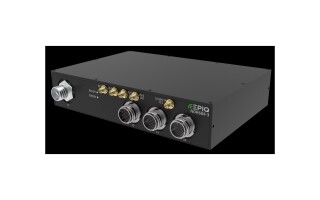
5G small cells should also exhibit low Df (or dissipation factor) values, which will rise as a function of frequency, to minimize dielectric circuit losses. Circuit materials with minimal moisture absorption, especially in outdoor cells, can minimize the dielectric losses caused by water absorption in high humidity environments. Specification of smooth conductors can also help minimize conductor losses at mmWave frequencies. The combination of low conductor and dielectric losses greatly aids hybrid mixed-signal circuits which may include radio transceivers operating at mmWave frequencies; microprocessors; data converters running at multigigabit rates; and the wide assortment of high-frequency, high-speed components and surface-mount technology (SMT) devices employed on 5G small-cell PCBs: low-noise amplifiers (LNAs), power amplifiers (PAs), and digital attenuators. (Figure 1)
Given the need to transmit signals from such small enclosures, 5G small cells also flirt with the effects of internally generated heat, from active components such as PAs and resulting from excessive circuit losses. PCBs for 5G small cells should have thermal-management capabilities that can safely conduct heat away from heat-generating components and the components and circuit surrounding them and to outside the small cell enclosure. A critical material parameter, coefficient of thermal expansion (CTE), provides insight into how a circuit material changes physically as a function of temperature, in all three axes, so that it can also provide a means of evaluating different circuit materials for the durability of plated through-holes used to interconnect multiple circuit layers.
Sorting solutions
With the high device densities and hybrid natures of PCBs in 5G small cells, practical circuits must be built for stable but exceptional electrical behavior as well as outstanding mechanical behavior even in outdoor operating environments. In addition to performance, there is the manufacturing aspect: Favorable circuits for 5G small cells should also be process-compatible with commonly used circuit materials, such as FR-4, which may also appear within a 5G small-cell enclosure and part of the production line for 5G small-cell PCBs.
Low-loss substrates can be used, as they have high dimensional stability across temperature and humidity; feature less loss than traditional FR-4 circuit materials at higher frequencies; and are process-compatible with FR-4 materials to help speed and simplify the steps needed to fabricate multilayer circuit assemblies for 5G small cells.
All three substrates employ low-profile copper conductors which contribute to low loss in HSD circuits and low passive intermodulation (PIM) in antennas and other analog mmWave circuits. The substrates feature good dimensional stability with temperature, which minimizes physical changes with temperature for good soldering accuracy. Another boon: Extremely low moisture uptake so that even in high-humidity operating environments, increases in signal loss due to moisture absorption will be minimal, even at mmWave frequencies. For processing purposes, all three are characterized by a glass transition temperature (Tg) of +200 °C.
More specifically, I-Tera MT40 (RF/MW) laminate and prepreg materials have a typical Dk of 3.45 at 10 GHz as measured through the z-axis (thickness); When less loss is required at a lower Dk, Astra MT77 laminates and prepregs; the third, Tachyon 100G laminates and prepregs materials (Fig. 3), are well-suited for HSD circuits of 100 Gb/s and faster in 5G small cells. They have a Dk through the z-axis of 3.02 at 10 GHz which remains constant for operating temperatures from -55 °C to +125 °C and Df of 0.0021 at 10 GHz. All of these share a low rate of moisture absorption of 0.1%. (Figure 1.)

[Figure 1 | Once network coverage has been achieved at higher millimeter-wave (mmWave) frequencies of 24 GHz and higher, 5G networks will support multigigabit upload and download speeds.]
PCB assemblies within 5G small cells will be densely packed with components to maximum analog and digital functionality while delivering the consistency and reliability needed for modern 5G wireless networks for military, defense, and other mission-critical communications services. What is found in those PCB assemblies will serve as foundations for the high-speed data and mmWave signals moving to and from the 5G small cells, performing in all seasons and at all temperatures. How these circuit layers are built will be critical to determining the successful operation of 5G wireless networks at mmWave frequencies.
Alexander Ippich is Signal Integrity & Advanced Technology, Product Manager RF/Microwave, OEM Marketing Europe, Isola.
Isola https://www.isola-group.com