Designing and testing for reliability: Ruggedizing vetronics to survive
StoryApril 29, 2011

Curtis Reichenfeld
Curtiss-Wright

When using COTS for ruggedized vetronics systems and subsystems, designing in cutting-edge technologies ? such as metal matrix composite enclosures ? and employing test methodologies including MEMA, RGT, and SRT will help ensure Size, Weight, Power, and Cost (SWaP-C) success.
A key challenge when ruggedizing COTS-based vetronics for military platforms is posed by the necessity of using available commercial and industrial components in most electronic systems. MIL-STD components (-55 °C to +125 °C) are either not available, or they are neither practical nor economical. As a result, subsystem designers must carefully analyze and test the thermal management features of the rugged system to ensure optimal performance and reliability in harsh combat environments before it is deployed. Making matters worse, more extreme operational temperatures than those specified in the past for military environments, such as those of the desert environments in Iraq and Afghanistan, are now commonly confronted.
Today’s rugged military systems are typically designed for ambient operating environments ranging from -40 °C to +71 °C. The electronics, such as computer boards, integrated into contemporary ruggedized subsystems are specified to perform at -40 °C to +85 °C at the card edge. These thermal management challenges make it difficult to cool today’s advanced electronics with a natural convection-cooled chassis, but a metal matrix composite enclosure is key in thermal management.
Moreover, to achieve Design For Reliability (DFR) with COTS, the sub-system needs to be designed to survive and perform over the extreme temperature range combined with intense shock and vibration. It also needs the necessary reliability and availability to perform the mission. To ensure these levels of reliability, subsystem integrators are going beyond their traditional responsibility to provide advanced testing and analysis of components from third-party suppliers to guarantee performance and quality.
To achieve DFR beyond thermal management requires a full range of techniques including component analysis, subsystem-level testing, Environmental Stress Screening (ESS), infant mortality testing of system-level components, the use of redundant elements, intelligent power, and health management. Thermal analysis and simulation are additional powerful tools that enable the system designer to discover potentially harmful hot spots and to redesign to improve overall system reliability.
The following discussion examines a new metal matrix composite enclosure designed to help the system continue reliable operation in extreme environments, in addition to a case study of a vetronics subsystem where RGT, SRT, and MEMA tests were performed.
Metal matrix composite enclosures beat the heat
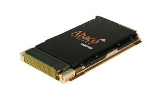
On the cooling front, one promising approach for significantly extending the thermal management limits is the use of new enclosure designs that use proprietary advanced composite materials to both increase cooling and lower weight, a breakthrough for Size, Weight, and Power- (SWaP)-constrained applications. This new class of enclosure uses a mixture of metal matrix composite materials to provide 2-to-3x greater thermal conductivity than is available from aluminum alone (Figure 1). The technology comprises a unique thermally efficient composite core housed within a structural composite shell. This makes it possible to provide the cooling performance of copper without the 3x weight penalty, not to mention the higher cost. Recent test results of the composite enclosure technology using a baseplate-cooled 3U VPX or CompactPCI enclosure showed a 2.4x increase in thermal conductivity at the chassis level (2.4x decrease in sidewall temperature rise), along with a 10 percent weight decrease compared to aluminum construction. The ability to thermally manage higher-power circuit cards has become increasingly critical, as leading-edge multiprocessing and DSP system designs accelerate their use of new technologies such as multicore processor-based VPX board architectures.
Figure 1: Metal matrix composite enclosure
(Click graphic to zoom)
|
|

This new enclosure technology offers the potential to enhance the weight and thermal performance of natural convection-cooled, forced air conduction-cooled, or liquid conduction-cooled chassis through superior heat spreading.
Design for reliability: A case study
A real-world example of the value of DFR recently occurred. The challenge was to cool a vehicle and mission control subsystem on a military vehicle in a +71 °C ambient environment in dead air without fans or ventilation. Aggressive field and laboratory testing of the vehicle’s subsystem resulted in a highly reliable product. The test methods used included qualification, Reliability Growth Testing (RGT), Statistical Reliability Testing (SRT), and hybrid MEMA SRT/RGT. The test technologies included traditional Single-Exciter Single-Axis (SESA) ElectroDynamic (ED) shakers, Multi-Exciter Multi-Axis (MEMA) ED shakers (Figure 2), and pneumatic repetitive shock. All the tests were performed using the procedures defined in MIL-STD-810G, with the exception of HALT, which exceeded the standards. A closer look at these testing methodologies is warranted.
Figure 2: Multi-Exciter Multi-Axis (MEMA) Electrodynamic shaker
(Click graphic to zoom by 1.9x)
|
|

RGT testing
RGT testing was used to determine temperature and voltage, the SESA random vibration, pneumatics and temperature, and SESA repetitive shock and temperature values. To assess its temperature and voltage, the subsystem underwent high then low temperature in its vehicle orientation. Temperatures were stepped, and for a given voltage, a full Acceptance Test Procedure (ATP) was performed. To determine the SESA random vibration, a unit was placed on an electrodynamic or hydraulic shaker and submitted to one complete life at an exaggeration factor of 3.5, followed by another run at 4.5. To determine the value for pneumatics and temperature, the unit underwent high Grms impacts from a pneumatic hammer. Stepped stress was applied at the operational low then high temperatures. An eight-hour endurance test was then run at 25 Grms, with half the time at the operational low temperature and the other half at the high temperature.
The SESA repetitive shock and temperature testing comprised multiple single-axis shocks in an attempt to determine if single-axis shock can provide similar results to multiple axis, or whether it is required to have a combination of multiple directions to uncover latent defects. The amplitude of the shock was increased in 20 g increments until failure occurred. Duration and shock pulse were not varied to maintain spectral consistency of the Shock Response Spectrum (SRS). In each axis, 50 shocks were applied at the low-temperature design level and 50 more at the high-temperature requirement for a combined environment input.
SRT testing
SESA random vibration and temperature is used to determine a reliability prediction within a desired statistical confidence level, based on the assumption that mechanical energy and thermal energy are the primary drivers of fatigue in a product. This testing comprised life testing at the design’s high temperature for one axis, followed by another life test at the design’s low temperature, with this sequence repeated for all three axes.
MEMA RGT/SRT hybrid testing
The subsystem also underwent a hybrid test that combined MEMA, RGT, and SRT. MEMA testing involved controlled random vibration excitation in multiple axes simultaneously. The shaker system used for this test had eight electrodynamic shakers that provided 6-DOF motion (three translational and three rotational).
Of the test technologies used, MEMA shaker technology produced the greatest ability to apply test results to reliability information. MEMA vibration testing was used to reduce laboratory test durations and increase laboratory test fidelity of the military ground vehicle. A MEMA shaker utilizes multiple single-axis actuators coupled into one shaker head, enabling simultaneous shaking of a test article in multiple degrees of freedom. This test method is inherently more realistic to field stresses and can reduce laboratory test durations by 66 percent. Testing the subsystem provided a realistic example of a complicated mission-essential LRU with extensive laboratory and field information; thus, MEMA testing could directly compare other methods of verification and validation.
Accelerated Life Test (ALT) via vibration stress is often used to provide qualitative and quantitative levels of confidence in the reliability and ruggedness of a product before it is deployed into the field. Choosing the appropriate test program can be difficult, depending upon the available cost and schedule to meet an acceptable risk threshold. MEMA testing promises to be a viable testing method to address cost sensitivity and schedule risks, and to provide high-failure mode and cause fidelity.
Demand for rapid deployment of the vehicle required that units be fielded in parallel with laboratory test efforts. Laboratory test methods were used to replicate all field defects. The design changes implemented as a result of the defects detected, in combination with ESS of the assembly, prevented any failures on the most recent version of the subsystem in the field. All described subsystem tests were performed by Curtiss-Wright Controls Electronic Systems.
Keeping pace with new ruggedization trends
Designers of rugged vetronics systems must continuously adapt to emerging military system needs, understanding and anticipating the latest requirements for cooling and SWaP-C that continually drive advances in the approach to ruggedizing vetronics. One example of a trend that will drive new approaches to ruggedizing vetronics is the emergence of smaller military vehicles designed to hit price targets derived from the commercial automotive realm. To meet these needs, system integrators will have to come up with new approaches to ruggedize for smaller, more affordable vehicles. These new electronics developments such as new SWaP- and heat-efficient composite metal enclosures – combined with MEMA and RGT/SRT testing – will drive new ruggedization approaches and design for reliability.
Editor’s note: Curtiss-Wright Controls has two separate and distinct divisions working on embedded technologies. This article was written by CWCEL (Curtiss-Wright Controls Electronic Systems).
Curtis J. Reichenfeld, P.E., is the Chief Technical Officer at Curtiss-Wright Controls Electronic Systems. He has more than 25 years of experience in safety-critical hardware and software for military electronic systems. He can be contacted at [email protected].
Curtiss-Wright Controls Electronic Systems 661-257-4430 www.cwcelectronicsystems.com