Multicore DSP enhances Synthetic Aperture Radar processing
StorySeptember 10, 2013

Dan Wang
Texas Instruments
Murtaza Ali
Texas Instruments

Multicore DSPs allow power-efficient implementation of SAR processing tasks.
Synthetic Aperture Radar (SAR) utilizes the relative motion between the antenna and the target region to create an effect of a larger antenna than the actual physical size, thereby achieving high-resolution remote sensing. Different Commercial Off-the-Shelf (COTS) architectures have been applied to SAR systems to accomplish the signal processing tasks, such as the IBM cell-based platform, CPU, General Purpose Graphics Processing Unit (GPGPU), and FPGA. Considering both the intense computational efforts and the need to put these systems onboard during flight, the current challenge is to form a high-resolution image in real time with low power. To solve this problem, complex synthetic aperture processing can be implemented in low-power embedded processors like a multicore Digital Signal Processor (DSP).
Basics of a SAR system
The complexity of SAR processing can be understood by studying the geometry of SAR signal acquisition. A SAR system gathers signals reflected from the targets at different positions at different times. The radar is usually carried by a spaceborne or airborne platform that moves with a certain speed along a desired track. The antenna transmits a short chirped waveform with a Pulse Repetition Frequency (PRF). The reflected echoes from the scene are collected, digitized, and stored by the antenna for later processing. The range direction is perpendicular to the azimuth direction, which is parallel to the flight track.
The original data collected from the radar is unfocused. To observe different targets in the scene area, the raw data passes through a chain of signal processing steps to achieve digital focusing. The first and most widely used method is the Range-Doppler (RD) algorithm. Other methods to focus the raw data on include the omega-K and the back-projection techniques. These techniques are much more computationally intensive compared to the RD method. The RD method features block processing efficiency and separability in two directions, so it is very suitable for parallel computing platforms. The following implementation is based on the RD algorithm.
Working with a multicore DSP architecture
Both the block processing and parallel nature of RD technique can be exploited using a multicore DSP. A typical multicore DSP can have several levels of parallelisms. First, the multiple (usually symmetric) cores can run multiple tasks at the same time. The cores can have multiple units that can run parallel instructions in the same cycle. Each unit within the architecture can also have Single Input Multiple Data (SIMD) instructions. The challenge is to map the computations efficiently to these different levels of parallelism to get the most power-efficient implementation.
In addition, these processor architectures also have memory hierarchy. This hierarchy consists of a set of internal private memories usually arranged in L1 and L2 configuration, internal shared memory, and DDR3-based external memory. Multicore DSPs usually offer additional configurability of these memory spaces, for example, the L1 and L2 memory can be configured as either cache or SRAM or as part cache/part SRAM. Efficient data movement across this memory hierarchy is another important consideration for implementing complex computations like SAR processing. The Direct Memory Access (DMA) mechanism is often employed for this purpose.
RD algorithm implementation
An efficient DSP implementation of an RD algorithm requires that each of the sequential tasks in the overall processing chain is efficiently mapped to the DSP architecture. The main sequential tasks involved in the RD algorithm are: range compression, matrix transpose, Range Cell Migration Correction (RCMC), and azimuth compression.
Range compression
Range compression is to compress the received pulse along the range direction to concentrate the main energy into a narrower duration. After range compression, target points having the same slant range of closest approach are collapsed into a single trajectory. Compression is achieved with match filtering, which is implemented as complex multiplication in the frequency domain. Figure 1 shows the implementation flowchart for range compression involving FFT, multiplication, and IFFT. The raw data is originally stored in the external memory DDR3. Data patches are fetched into the local L2 memory via DMA. The reference function and the twiddle factors for FFT/IFFT are precomputed and stored in the shared memory.
Figure 1: Data movement and computations are optimized for range compression.
(Click graphic to zoom by 1.9x)
|
|

Matrix transpose rearranges the range of compressed data so that it can be read and processed along the azimuth direction. The range compressed data stored in DDR3 are grouped into squared blocks to achieve higher DMA transfer efficiency. Block size is bounded by the available L2 memory space. Similar to the range compression, the ping-pong strategy is applied to improve the efficiency by overlapping the DMA operation and the data processing stage.
RCMC and azimuth compression
Range migration is caused by the range variations resulting from platform movement. Range migration correction adjusts distance at each radar position, so that the slant range appears to be constant. From the implementation perspective, the goal of RCMC is to rearrange the data in the memory to straighten the trajectory. After RCMC, azimuth compression can be conducted along each parallel azimuth line. Note that the migration for the whole family of targets with a same range distance is corrected simultaneously in this Range-Doppler domain method.
To implement RCMC, FFT along the azimuth direction needs to be carried out first. Therefore, we can treat RCMC as a part of azimuth compression. Similar to range compression, patch FFT strategy is applied to improve the DMA efficiency. The twiddle factors are precomputed and stored in the shared memory. After azimuth FFT, data in DDR3 are loaded to L2 as squared blocks. RCMC is implemented as a 16-set 8-tap filter. The interpolation coefficients are precalculated and stored in the shared memory. The fractional part of the migration amount determines the coefficient set, and the integer part decides the shift amount. Finally, the corrected data in the output buffered in L2 memory are transferred to DDR3. Figure 2 shows the detailed implementation of the RCMC and azimuth compression.
Figure 2: Data movement and computations are optimized for RCMC and azimuth compression.
(Click graphic to zoom by 1.9x)
|
|
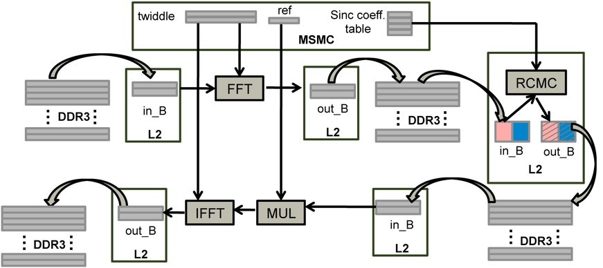
It is worth mentioning that the data to be read for interpolation at each correction are along the range direction. However, after matrix transpose, data are organized in the azimuth direction, so data used for interpolation are no longer continuously stored in the memory. This memory access discontinuity leads to additional cost during interpolation for RCMC.
Azimuth compression is the last step to generate a focused image. Each azimuth line collapses into a single point after compression. It is similar to range compression. The main difference is that the azimuth reference is range dependent. For simplicity, the current implementation assumes that the azimuth reference function is constant at all range cells.
Assigning memory through multicore mapping
As already noted, the RD technique is amenable to parallel implementation. A data parallel model is used in our implementation. Each core is simply assigned a different portion of data to process. At each stage, the data in the external memory are divided into eight portions. Each core retrieves the data according to the start point of the allocated location through DMA, and writes data to the assigned memory portion in DDR3 after local processing. The access to the DDR3 memory among multiple cores is scheduled by the DMA controller. The OpenMP runtime on the multicore DSP will run multiple threads (one thread per core) with their own allocated data portion.
Illustrating application benchmark performance
To provide some application benchmarks to illustrate the performance of the aforementioned design, we implemented it on a TMS320C6678 evaluation board available from Texas Instruments and profiled the execution time for each procedure in the RD algorithm. The applied image size is 4096 by 4096, which is very typical for a prototype SAR test. This results in 4096 FFTs and IFFTs in each transformation. The actual FFT size varies widely for different SAR applications. Very small FFT might be necessary for auto-focusing algorithms and very large FFT size might be needed in azimuth direction for full-resolution SAR image formation. In most cases, allowed FFT/IFFT size is limited because of the small local memory size. Therefore, one can divide the large image into patches and use smaller FFT sizes with overlap-save/add strategy for range/azimuth compression.
As expected, the time required for range compression and azimuth compression scales very well with the number of cores. With 8 cores, we obtained a speed-up factor of 7.9. On the other hand, the corner turning timing, RCMC, and azimuth FFT saturate at around 4 cores. This is because these steps are memory I/O bound, especially for matrix transpose.
The range compression and RCMC are the most computationally intensive steps. The sum of azimuth FFT and azimuth compression is similar to that of the range compression step. For the total execution time, it takes around 0.25 seconds to process the whole 4096 by 4096 image using 8 cores in parallel, with an acceleration factor of 6 relative to the single core case. Given that this processing is done with a 10 W device, this execution time makes the multicore DSP very competitive among other alternatives, such as GPGPU and CPU, as discussed earlier. Further, since the SAR processing is embarrassingly parallel, multiple devices can be employed to further improve the throughput.
Making DSP SAR systems efficient, scalable
Synthetic aperture radar systems require intense computational effort because of the large data size and complicated processing procedures. Considering the power efficiency and computational capability of new generations of multicore DSPs, designers can use such a platform as a candidate for SAR implementation. The computation tasks can be easily distributed to multiple cores and data processed in parallel. The scalability of SAR operations across multiple devices also bodes well for DSPs to provide embedded platforms suited to wide variations in SAR applications. The benchmarking results show that, with an image size of 4096 by 4096, the processing frame rate is 4 frames/second, achieving real-time performance with a 10 W multicore device.
Dan Wang is a Member of Technical Staff at Texas Instruments. She is an expert in signal processing theory and implementation. She is currently involved in the development of radar technology, especially for automotive applications. Dan can be reached at [email protected].
Murtaza Ali is a Distinguished Member of Technical Staff at Texas Instruments. He leads the High Performance Compute and Radar R&D activities in the Embedded Processing Systems Lab. Murtaza is a senior member of IEEE. He can be reached at [email protected].
Texas Instruments 972-341-2544 www.ti.com