Cooling the beast: Heat-dissipation techniques for next-gen processors
StoryAugust 29, 2018

Jeremy Banks
Curtiss-Wright

The good news: Newer-generation processing devices offer hugely boosted capability for military applications such as airborne data processing, shipboard electronics, or ground vehicle systems. The bad news: Newer-generation processing devices offer much more capability. Is this really both good news and bad news? In a word, yes.
In the world of FPGA [field-programmable gate array] processing and I/O, a standard improvement on generation-to-generation advantage is typically 30 percent less power per gate, but the number of gates in the device doubles, which means that while there’s a performance increase, there’s also an increase in power and heat generated, assuming you’re looking to use all of the functionality of the device. A mid- to high-range FPGA could easily be expected to consume 100 watts of power in a single device. If other power sources and power supply efficiencies are factored in, the overall power that needs cooling rises rapidly.
Power – or more specifically heat density – has increased, with more to come. Bottom line: Cooling challenges have increased, not decreased, for high-end computing. For other devices, similar functionality has been squeezed into a smaller package.
For example, some newer A/D converters have adopted serial interfaces like JESD204B, moving away from the original parallel ports in order to reduce the number of interface pins needed and use a smaller package. These devices use about the same amount of power, but the shrinking package advantage can be quite significant. Such a change could result in a heat density increase of between 200 and 400 percent. A typical high-speed A/D converter could be a few watts; while they’re not the hottest devices, the heat density means that attention has to be paid to cooling – especially if a number of devices are stacked side-by-side.
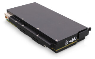
In general, higher levels of integration is good news, as more can be fitted into a smaller overall system or board footprint leading to fewer cards. The overall solution is smaller and likely lower in cost. However, increased heat density – even with fewer cards and smaller devices – requires additional considerations for cooling the system, especially if this is a rugged system needed to work in wide-temperature-range environments. High-end, new-generation systems, such as those based on the VPX standard, especially need careful consideration. Even if all the necessary functionality fits on the minimum number of cards, it may still be worth spreading out this functionality to cool the system effectively. In the same vein, reaping the benefits of smaller, higher-performance systems means careful focus on efficient cooling. An example of a new 3U VPX card design from Curtiss-Wright squeezes in a large Virtex UltraScale+ FPGA, a Zynq UltraScale+ MPSoC (including quad A53 ARM CPUs), two 6 Gsps A/D converters, two 6 Gsps D/A converters, and a supporting ensemble of other functions. All deliver higher performance functionality, but such levels of integration require just as much effort for cooling as it does for RF speed I/O and high-end FPGA processing. (Figure 1.)
Figure 1: VPX3-535 shows an example of a VITA 48.8 AFT design. Illustration courtesy Curtiss-Wright.
|
|

In the VPX board format world, the primary cooling methods are air cooling (AC) and conduction cooling (CC). AC relies on air being driven or pulled across cards with primary high-power devices, usually having a heat sink to help remove the heat. Both formats tend to use aluminum heat sinks and heat frames; but other materials are used as well, such as copper or other high-conductivity compounds, which improve thermal conduction. However, these materials also add weight and/or cost.
CC is usually used in high-altitude environments where there is low air pressure, or for use in systems that are sealed to external air sources. For a 3U VPX card, conventional cooling limits the power dissipation of a board to less than 100 watts and still be able to maintain an 85 °C card edge temperature. However, for higher-powered parts – say 150 to 200 watts – something more is needed if boards are required to operate in a high ambient temperature environment. There are a number of alternative cooling strategies to deal with these much higher power requirements – such as liquid cooling and spray cooling – but these have often been seen as exotic because of the 10 or even 20 times price premiums. These techniques still have their place (and quirks), but perhaps a more recent development that raises the bar is Air Flow Through (AFT).
AFT for VPX is supported with variations (“dot specifications”) through VITA 48. In some ways, AFT is a hybrid between air and conduction cooling, but with greater cooling capability. AFT relies on a heat frame that clamshells onto the entire board’s electronics. An AFT heat frame includes a closed duct, which is embedded with fins. Air is routed through these ducts to provide cooling. Air does not blow across any of the board’s electronics directly, which also ensures that there is no contamination. This efficient use of air for AFT schemes enables significantly increased cooling capabilities for only a modest increase in system infrastructure. AFT supports in the region of 200 watts of cooling capability needed to handle high density processing and I/O solutions.
One common trade-off – if it really is a trade-off because of the increased possibility of higher integration – is the increased slot pitch, which might typically be 1 to 1.5 inches. What makes AFT more efficient, compared with solutions like conduction cooling, is the lower thermal impedance. For a CC solution, air might be used to cool the chassis sidewalls. The CC module is positioned in card guides that are part of the sidewalls. Heat flow occurs from the electronic parts into the card’s heat frame, across the card edges (which are retained in the card guides by wedge locks), into the card guides, and finally into sidewall air flows.
AFT is more direct, as the air is blown directly through the card’s heat frame, though – like the conduction-cooled solution – the card’s electronics are still sealed and protected from the outside world. The more direct cooling method provides lower thermal impedance, which means more heat can be removed for a given ambient air temperature, which in turn enables either high-power operation or tolerance of higher ambient temperatures. (Figure 2.)
Figure 2: Comparative thermal plots showing conduction and AFT cooling of a similar VPX3-535 design.
|
|

Table 1 shows a comparison between similar cards with different cooling techniques and different materials analyzed through simulation to get the comparisons. The primary FPGA is used as a temperature reference as it is the hottest device and therefore the limiting factor. The ambient temperatures are equivalent when taking into account the temperature of air or effective card edge temperature for the conduction-cooled equivalent (air inlet +63 °C, card edge +71 °C). In all cases the FPGA is assumed to be dissipating 90 watts.
Table 1: Cooling comparison between a similar design in conduction and AFT variants.
|
|

In being able to squeeze the most performance out of a design, every degree counts. What’s more, better cooling increases the part’s in-service lifespan. It may seem that the design works at high ambient temperature, but for how long? Aluminum, the default material used for cooling, has a fair amount of capability; an immediate improvement can be gained from using copper, but that comes with a high weight penalty and increased cost. AFT using standard aluminum beats copper when all thermal impedances are taken into account.
Within the VITA domain, there are a number of AFT variants, differing in slot positions and some carrying proprietary IP and patents, but all essentially do the same thing, differing only in the mechanics of how the air flow is achieved. VITA 48.8 is simple and royalty-free, plus it does not require wedge locks (they reduce the air opening/duct size), so there is even more PWB real estate to use for the board design.
Different cooling techniques offer different advantages depending on the application’s needs and environment. AFT offers a new option without outrageous cost implications and will meet the cooling demands of future rugged designs.
Jeremy Banks is Product Marketing Manager, Curtiss-Wright Defense Solutions. He holds a BSc (Hons) in electronic and electrical engineering from the University of Surrey, UK.
Curtiss-Wright Defense Solutions www.curtisswrightds.com