SpaceVPX and the world of interconnect
StoryJune 18, 2020

By C. Patrick Collier and Michael Walmsley
Open standards have been driving innovation more quickly to the end user in aerospace and defense applications for decades and now space systems are truly enbracing them. A perfect example is the SpaceVPX standard, which leverages the OpenVPX architecture through the interconnect solutions defined in VITA standards. This piece from SpaceVPX founder Patrick Collier and Michael Walmsley of TE Connectivity, the designers of the VPX and SpaceVPX interconnect, covers the basics of SpaceVPX, recent changes, and the importance of the standard interconnect, which drives down cost, results in a more robust supply chain, and maintains a path for future expansion.
SpaceVPX, originally named The Next Generation Space Interconnect Standard [NGSIS), is a government-industry collaboration effort to define a set of standards for interconnects between space system components with the goal of cost effectively removing bandwidth as a constraint for future space systems. This effort builds on the VITA [VMEbus International Trade Association] OpenVPX standard and extends it for space applications.
The NGSIS team selected the OpenVPX standard family as the physical baseline for the new SpaceVPX standard because VPX supports both 3U and 6U form factors with ruggedized and conduction-cooled features suitable for use in extreme environments.
Built upon several standards that are part of the ANSI/VITA OpenVPX family, including the base VITA 46 VPX standard and its ANSI/VITA 65 OpenVPX derivative, SpaceVPX also allows other compatible connectors to be used, including ANSI/VITA 60 and 63. ANSI/VITA 48.2[3] forms the base of the mechanical extensions in SpaceVPX while ANSI/VITA 62 defines a standardized power module. ANSI/VITA 66 and 67 also may be applied to replace electrical segments of the connector with RF or optical solutions. ANSI/VITA 46.11[4], currently in trial usage, provides a base of the management protocol that SpaceVPX builds upon for fault-tolerant management of the SpaceVPX system.
Organizing connections
Four major interconnect planes organize the connections in OpenVPX – data, control, utility, and expansion. The data plane provides high speed multigigabit fabric connections between modules and typically carries payload and mission data. The control plane, also a fabric, typically has less capacity and is used for configuration, setup, diagnostics, and other operational control functions within the payload as well as lower-speed data transfers.
The utility plane’s function is to provide setup and control of the basic module functions that typically handle power sequencing and low-level diagnostics, as well as the power, clocks, and other base signals needed for system operation. The expansion plane may be used as a separate connection between modules using similar or bridging heritage interfaces in a more limited topology such as a bus or ring. Pins not defined as part of any of these planes are typically user-defined and are available for pass-through from daughter or mezzanine cards or to rear transition modules (RTM). For maximum module reuse, the user-defined pins should be configurable so as not to interfere with modules that use these pins in a different way; consult ANSI/VITA 65 for more detail.
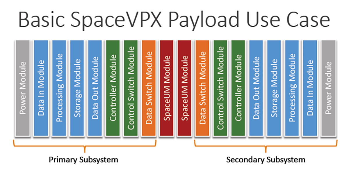
[Figure 1 | SpaceVPX’s goal: To achieve an acceptable level of fault tolerance by way of redundancy and switching. Illustration: VITA.]
Major changes in SpaceVPX
In evaluating the use of OpenVPX for potential space usage, several shortcomings were noticed. The biggest one was the lack of features that could support a full single-fault-tolerant and highly reliable configuration. Utility signals were bused and in most cases supported only one set of signals, via signal pins to a module. A pure OpenVPX system has opportunities for multiple failures, as a result.
A full management-control mechanism was also not fully defined with VITA 46.11. The fact that the typical OpenVPX control planes are PCI Express or Ethernet was another shortcoming of concern since their usage in space applications was minimal; moreover, SpaceWire is the dominant medium-speed data and control plane interface for most spacecraft. A third area was the desire to reuse the infrastructure of OpenVPX for prototyping and testing SpaceVPX on the ground.
Mission: Fault tolerance
The goal of SpaceVPX is to achieve an acceptable level of fault tolerance, while maintaining a reasonable level of compatibility with existing OpenVPX components – this includes connector-pin assignments for the board and the backplane (Figure 1.) For the purposes of fault tolerance, a module (defined as a printed wire assembly which conforms to defined mechanical and electrical specifications) is considered the minimum redundancy element. The utility plane and control plane within SpaceVPX are all distributed redundantly, and are arranged in star topologies to provide fault tolerance to the entire system.
Meeting that level of fault tolerance required the utility plane signals to be dual-redundant and then switched to each SpaceVPX card function. A trade study was performed early to compare between various implementations including adding the switching to each card in various ways as well as creating a unique switching card. The latter approach was chosen so that SpaceVPX cards could each receive the same utility plane signals that an OpenVPX card receives with minor adjustments for any changes in topology. This became known as the Space Utility Management (SpaceUM) module and is a major contribution of the standard.
The SpaceUM module contains as many as eight sets of power and signal switches to support SpaceVPX modules. It receives one power bus from each of two power supplies and one set of utility plane signals from each of two system controller functions required in the SpaceVPX backplane. The various parts of the SpaceUM module are considered extensions of the power supply, system controller, and other SpaceVPX modules for reliability calculation and thus do not require their own redundancy.
Profiles for space defined
Since each slot, module, and backplane profile in OpenVPX is fully defined and interlinked, the changes made for SpaceVPX require a SpaceVPX version of each of these profiles to be specified. Specifically, the slot profiles provide a physical mapping of data ports onto the slots’ backplane connector, which is agnostic to the type of protocol used to convey data from the slot to the backplane.
The module profiles are extensions of their accompanying slot profiles that enable mapping of protocols to each module port. Each module profile includes information on thermal, power, and mechanical requirements. Many are very close to OpenVPX and thus should enable use of OpenVPX modules and backplanes for prototyping or testing but are different enough to require full specification. The section of the SpaceVPX standard that defines profiles was a significant effort and forms a majority of the completed standard.
SpaceVPX interconnects
Interconnects are also a critical part of SpaceVPX and as with other elements of the standard are based on those interconnects developed for OpenVPX, but designed for the extreme space environment. For decades, designers for space applications used customized interconnect designs to ensure the reliability of embedded electronics exposed to the extremes of space. Problematic temperatures, vibration, outgassing, and other factors can catastrophically compromise interconnect systems and signal and power integrity. The high cost and long lead times of a custom interconnect solution were considered a worthwhile investment against failures that are either impossible to fix in space or extremely costly.
By leveraging the OpenVPX architecture, SpaceVPX brings in the interconnect solutions which are defined in VITA standards and have gone through extensive testing to support their use in space. The use of standard interconnects drives down cost, results in a more robust supply chain, and maintains a path for future expansion.
The SpaceVPX slot profiles define the use of VPX connectors (VITA 46 or alternate VPX connectors) and enable implementation of RF (VITA 67) and optical (VITA 66) modules at the plug-in module to backplane interface. Power supplies follow the VITA 62 standard, which also defines the power supply connector interface. For XMC mezzanine cards in plug-in modules, XMC 2.0 connectors per VITA 61 are recommended. SpaceVPX slot profiles pull in the appropriate VITA connector standards that support the OpenVPX architecture, rather than defining new connectors with special characteristics.
VITA 46 VPX connectors
The original VPX interconnect is the VITA 46 VPX connector, based on TE Connectivity’s (TE’s) MULTIGIG RT 2 connector, and was released in the VITA 46 standard in 2006. The MULTIGIG RT connector family gives designers an easy-to-implement, modular, standardized and cost-effective interconnect system that helps ensure the reliability of their embedded-computing applications for space systems. MULTIGIG RT connectors had been tested by TE and implemented in space applications before the origin of SpaceVPX.
The MULTIGIG RT connectors have gone through extensive testing by TE to establish suitability for space, including:
- Compliant (press-fit) pin technology: Testing has been performed by TE at min-max board hole sizes and different PCB [printed circuit board] platings to verify the reliability of the compliant pin designs. Today there are numerous space applications using compliant pin technology (versus the traditional soldered connections), and its implementation is growing.
- Vibration: To address extreme vibration applications, the VITA 72 study group was formed and devised a vibration test that subjected a 6U VPX test unit to random vibration levels of 0.2 g2/Hz for 12 hours, a severe requirement compared to the original VPX standard. TE’s MULTIGIG RT 2-R connector – featuring an enhanced quad-redundant backplane connector contact system and rugged guide hardware – tested successfully as part of this effort and was released in 2013 for highly rugged applications.
- Extreme temperature: MULTIGIG connectors were tested by TE to a temperature range of -55 ˚C to +105 ˚C when initially qualified for VPX in 2006, which met the VITA 47 standard for plug-in modules. In direct response to requirements from space-systems developers, MULTIGIG RT connectors have been tested and survived -55 °C to +125 °C, including exposure to 1,000 hours of heat at 125 °C and 100 thermal shock cycles from -55 °C to +125 °C.
- Outgassing: Unlike heavy polymer plug-in module connectors used in conventional backplane connector designs, MULTIGIG RT connectors incorporate air gaps, so less polymer is needed. The polymer reduction not only reduces weight but also outgassing. With MULTIGIG RT connector materials, total mass loss (TML) is less than 1% and collected volatile condensable materials (CVCM) is less than 0.01%, which meets NASA and European Space Agency (ESA) outgassing requirements.
- Current capacity: When VITA 78 was developed, there was a need for VPX connectors to support new pinouts (not defined in VITA 46) to support the requirements for redundant power distribution and redundant management distribution. TE completed extensive testing for current carrying capability on multiple adjacent MULTIGIG power wafers within plug-in module connectors and also released new wafer configurations to support the VITA 78 Space Utility Management module architecture.
Space system designers use these MULTIGIG RT connectors with minimal or no physical change – depending on user requirements – to the design or materials and finishes. Higher lead content (40%) in the contact tails may be specified for increased tin-whisker mitigation; in many cases, additional screening tests are required based on the user or program requirement, but the connector-manufacturing processes are relatively the same, which helps improve availability and cost.
RF and optical modules
There are options to integrate RF and optical connector modules within an OpenVPX slot to carry signals through the backplane to/from the plug-in module. These connector modules are mounted to the boards (including standard aperture cutouts on the backplane) to house multiple coaxial contacts or optical fibers and can replace select VITA 46 connectors within a slot. These RF and optical connector modules and contacts are compatible for space and have been implemented in satellite systems.
VITA 67 is the base standard for RF modules and are the initial standards defined in an SMPM RF interface for the contacts in VITA 67.1 and 67.2. An upcoming revision to the VITA 67.3 standard adds higher-density interfaces NanoRF and SMPS, which can increase the contact density two to three times over SMPM.
VITA 66 is the base standard for optical modules, with MT ferrules as the primary optical interface between the plug-in module and backplane as defined in VITA 66.1 and 66.4 standards. With the emergence of a new VITA 66.5 standard, higher-density modules are being defined featuring up to three MT interfaces in a half module, a significant increase in bandwidth density.
XMC connectors
XMC mezzanine cards can be implemented on SpaceVPX plug-in modules to add I/O and other features. In the SpaceVPX standard, the recommended XMC connector is VITA 61 XMC 2.0, the standard based on TE’s Mezalok connector. The Mezalok connector features multiple points of contact per pin, supporting the redundancy desired for space application. It has also been tested to extreme environments – including 2000 thermal cycles from -55 ºC to +125 ºC with no solder joint failures – and meets outgassing requirements.
The roadmap for SpaceVPX interconnect
By leveraging the OpenVPX architecture, SpaceVPX can also leverage the OpenVPX interconnect roadmap, which addresses solutions having faster speeds, higher density, smaller size, and lighter weight. There is significant activity with new and revised VITA standards to define technologies supporting next-generation embedded computing.
The upcoming revision to the VITA 67.3 standard introduces the higher-density RF interfaces NanoRF and SMPS, reducing size and weight – both of which are critical for space systems – and accommodating higher frequencies to 70 GHz.
The VITA 66.5 standard is in development, documenting higher-density optical interfaces, bringing up to three MT interfaces into a half-module and enabling integration of a fixed edge-mount transceiver. In addition, VITA 66.5 provides solutions with NanoRF contacts and optical MTs integrated into a common connector module, providing unprecedented density within an OpenVPX slot.
New VITA 62 power supply standards are addressing higher input voltages (270 VDC) and three-phase power configurations. New MULTIBEAM XLE connectors from TE with isolating fins provide this upgrade for higher voltage levels while maintaining the same VITA 62 interface.
C. Patrick Collier is open systems architect and systems engineer at Harris. Patrick Collier focuses on the development and use of open architectures for both space and nonspace applications. Previously he was a lead hardware engineer at PMA-209 NAVAIR, where he focused on the development of the Hardware Open Systems Technology (HOST) set of standards. His first assignment was as a senior electrical research engineer with the Air Force Research Laboratory Space Vehicles Directorate. While at AFRL, he founded the Next Generation Space Interconnect Standard (NGSIS) with Raphael Some (NASA JPL). Patrick also founded and is currently chair for the VITA 78 (SpaceVPX) and VITA 78.1 (SpaceVPXLite) efforts. He is also a cofounder of the Sensor Open System Architecture (SOSA) and chair of its Hardware Working Group. Additionally, he was a lead for the Space Universal Modular Architecture (SUMO), where he worked to incorporate existing space-related standards and architectures into SUMO.
Michael Walmsley, global product manager for TE Connectivity, has more than 35 years of experience with interconnects, primarily in engineering and product management roles. His areas of expertise include interconnect solutions for embedding computing, rugged high-speed board-level, and RF connectors. Mike is also associated with the VITA organization (www.vita.org), which drives technology and standards for the bus and board industry. He holds a bachelor’s degree in mechanical engineering from the University of Rochester and an MBA from Penn State.
Harris • https://www.harris.com/
TE Connectivity • https://www.te.com/usa-en/home.html