Hardware-in-the-loop simulation testing for defense and aerospace systems
StorySeptember 19, 2016


With hardware-in-the-loop (HIL) simulation testing, engineers are able to cost-effectively test aircraft components such as electronic control units (ECUs) and line-replaceable units (LRUs), running these components through complex scenarios.
HIL simulation is well-known in the automotive industry, enabling engineers to test embedded systems by simulating real scenarios. “HIL is putting hardware systems into control or measurement loops that will emulate or supplement behavior that you might get from a real-world part,” says Dave Baker, vice president of engineering at test-and-measurement automation company G Systems in Dallas, Texas.
Cost and functionality factor into any design and development phase of a system: “HIL testing is invaluable because it allows these dangerous or difficult tests to be conducted with a great deal of fidelity, which saves cost and improves safety and reliability,” says Bill Eccles, principal electrical engineer at automated test, data acquisition, and control system manufacturer Bloomy in Hartford, Connecticut. “Though manufacturers always test their products in the real world, there’s simply no way they can exercise them in all conditions.”
The scalability and maturity of this technology has enabled aerospace and defense companies to use HIL simulation to test RF signals. “That’s pretty revolutionary that someone is using HIL with RF signals,” says Adam Foster, senior product manager for test systems at National Instruments in Austin, Texas. “HIL is a big thing for aerospace and defense. It allows them to go after more corner cases in complex situations.”
HIL subjects the part “to signals and conditions similar to those found in the real world. These signals are under the control of models of the real world, which run in a real-time test environment,” says Eccles. The part “then produces signals which feed back to these models, and that makes a complete loop. The result is that the flight control, system computer, engine control, or whatever ‘thinks’ it’s happily flying or rolling along even though it’s stuck on a rack in a lab somewhere.”
Signal testing
HIL-simulation testing can be helpful when conducting coexistent-signal studies in radar applications. With the signal generator and spectrum analyzer, “one of the important elements for the hardware-in-the-loop studies for coexistence is the ability to do radar echo generation,” McCarthy states. Engineers can “set up a benchmark with the radar echo generator. You can put that at a runway at a fixed position, downrange of the radar, with ‘X’ number of signals at various amplitudes. Then as you introduce an interference signal, it could be cosite, it could be at an off-azimuth angle, it could be at a different amplitude or frequency,” McCarthy explains. At this point, he says, “you can start to test the immunity of the radar.”
The technology is also based on the same used in the wireless industry: “It is basically taking the communication technology used to create fading and multipath conditions to emulate cellphone propagation patterns.” The technology to create those multipath reflections is the same technology used to create echo returns in a radar, McCarthy notes.
Similar technology has been used in the automotive industry for several years to functionally test radars in a development and manufacturing environment and it has been used on military radar systems only within the last year or two, McCarthy says. “It has been starting to take off for people to functionally test the radar.”
With military radars, for example, “you can benchmark the radar and conduct a full functional performance validation of the radar by putting in different echo returns,” says Darren McCarthy, A&D technical marketing manager at Rohde & Schwarz USA in Beaverton, Oregon. “If your radar has the ability to receive a signal of -120 decibel-milliwatts (dBm) you can emulate ten targets offset in frequency, amplitude, and distance with ten returns.
“A couple dB each step and then you can test this sensitivity or selectivity of the radar as you introduced coexistent networks such as an LTE user device at a certain channel or frequency offset from that radar,” he continues. “By varying the frequency offset and amplitude, a complete evaluation of the radar’s performance and its susceptibility can be determined. By physically moving the coexistence signal to other angles of incidence, you can fully characterize the radar/antenna combination and come up with performance guidelines for the radar.”
An issue is that “radars don’t conform to any standard and so they don’t really have set guidelines of how close a cellular network can be in frequency and not impact the radar,” continues McCarthy.
Rohde & Schwarz has commercial off-the-shelf (COTS) vector signal generators and spectrum analyzers, such as the SMW200 and the FSW43 (Figure 1), that “basically receive a signal, loop it back, and then allow users to control offsets and targets using Doppler, doing attenuation to emulate different radar cross-sections. Then as targets move away you can choose to have a typical link budget roll off of what the typical target would do.”
Figure 1: The SMW200 and the FSW43 can create radar echoes up to 40 GHz. Photo courtesy of Rohde & Schwarz.
|
|

Using HIL testing for aircraft
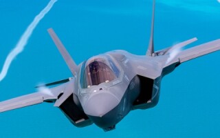
With airborne platforms, such as Saab Aerospace’s Gripen fighter aircraft, engineers used National Instruments’ HIL-simulation technology (Figure 2) for integration testing of its LRUs. “Saab Aerospace is focusing on HIL simulation to help drive down cost. Aircraft simulations can be done using physics models and using signal processing. It’s not all software but it does require some hardware functionality in it,” Foster says. “There are certain safety factors; you want to ensure you have as much test coverage in as many of the corner cases that this vessel or instrumentation could be put in.”
Figure 2: HIL simulation can be customized through open software, modular PXI and CompactRIO instrumentation, and signal conditioning (SLSC) modules. Photo courtesy of National Instruments.
|
|

Some simulations the aircraft can be placed in could be, for example, “If your airplane has engine failure, you need to be able to simulate how ECUs or LRUs are going to behave in these situations,” Foster continues. “HIL lets you simulate those things without having to do all of the physical tests for it. So you’re not going to have to build a prototype and staff it with somebody flying it and force them to do a nose-dive or blow up one of the engines.”
Essentially, “HIL tricks the LRU, or ECU, or onboard control unit into thinking it’s actually flying, and so it requires a lot of sophisticated instrumentation both to send the stimulus signal as it would be recorded or determined from physics models or recorded from empirical data,” he says.
Testing the aircraft requires the engineer to understand every minute detail of the aircraft, from what type of material the wing is made of, to how fast the airplane will go, to what the wind conditions look like with humidity, Foster explains. “All that simulation and information requires an immense amount of processing power, but what you do is you basically plug in the ECU and run it through various permutations of flying conditions and failure modes, all while you’re logging data.”
As software becomes more prevalent, the “microtrend of hardware-in-the-loop would be as we digitize everything, and as we switch from mechanical control to electronic control, you get the ability to test it and continue to squeeze cost out of it. All the while you are creating physics models and running simulations that would give you very reliable results between simulated and real,” he adds.
Signal coexistence and finding a common ground
What’s driving the industry to HIL simulation testing is more than just cost and functionality. The spectrum continues to be sold outside the military arena; with the coexistence of signals within the same spectrum, it has brought the industry to “look at coexistence studies and interoperating signals with the radars at the same time as communication systems,” McCarthy explains.
Bringing more commonality into test systems across the industry will help in setting a standard across the board. As the military adopts LTE technology, there is a need to complete the standards and finish adding the functions by the working groups, he says. “You need to have spectrum studies for coexistence and allocations of that spectrum, selling the spectrum, but you also need to set policy for interoperability.”
An ideal test-and-measurement industry would “have the same kind of architecture and basic platform design,” Baker notes. “For instance, we might have an I/O map or interconnect system and that I/O map would be shared across six different test systems. Even though all six of those systems don’t use the same map, we would reserve locations in that test system that would be common. You could replicate that many times and still support any of those six test articles.” MES
Sidebar 1
|
|