Project "Total Recall" case study: Designing a large rugged/redundant storage server
StorySeptember 23, 2009

Ken Owens
Conduant Corporation
The task: to design and build a massively redundant, ruggedized storage and computing subsystem, without the end application being disclosed. Meanwhile, challenges of backplane design, thermal dissipation, and ruggedization arose.
Recently, Conduant Corporation in Longmont, CO was subcontracted to design and build a massively redundant, ruggedized storage and computing subsystem. Although the end application was not disclosed, Conduant’s requirements included redundant servers each with redundant access to storage with a capacity of up to 2 TB. Challenges of backplane design, thermal dissipation, and ruggedization under weight constraints all needed to be conquered by the engineering team to satisfy the project requirements.
The challenge
The basic system called for a large storage farm of up to 2 TB connected to a server host along with eight processor boards for data manipulation and processing. For redundancy there had to be four independent servers and each server had to include a primary and secondary path to the storage farm. The active server and processing boards were required to have network access to each other and externally using a GbE LAN. A final major requirement was that power to all components must be individually controllable for power conservation. This included each individual storage device. The entire configuration had to be contained in a ruggedized chassis measuring 17" x 12" x 11", cooled only by conduction, and able to survive high vibration and shock levels. Thus, the primary challenges were designing the backplane, thermal dissipation, and meeting these specific ruggedization stipulations. A look at the overall design is necessary before delving into these challenges.
The design
The design task included selection and qualification of the major COTS components, development of the custom backplane, and the mechanical design of the chassis. Software integration support and all testing to qualify and demonstrate the required functionality were also performed.
The major components selected for the system include the single board computer, which has a dual-core 64-bit CPU running at 2 GHz, solid-state SATA disks, and a 10-port GbE switch. There are also DC/DC power supplies and an EMI power filtering module. Although the system dissipates more than 400 W, no fans or other convective cooling devices could be used; conduction cooling to a customer supplied cold plate was specified. The proposed ambient operating environment ranged from -5 °C to +50 °C with the customer supplied cold plate at up to 50 °C.
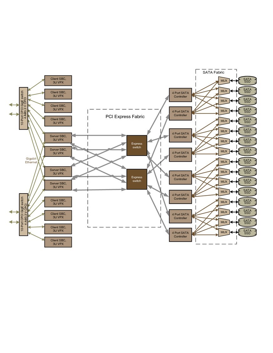
Conduant designed a custom backplane to accommodate the 12 SBCs, 16 SSDs, 6 DC/DC power supplies, and the 2 GbE switch boards. The components were a mix of conduction-cooled 3U CompactPCI and VPX. The backplane also had to include the SATA connectors to allow the SSDs to connect directly to the backplane. The SSD storage device was mounted on a carrier to fit a standard 3U conduction-cooled chassis slot. This allows easy removal/replacement of the SSDs for service or expansion. Four of the CPUs are designated as servers with one active as the other three stand in reserve. The remaining eight CPUs are utilized as processing centers and communicate with the active server CPU for storage access over the internal Ethernet LAN. With the design in mind, the engineering team was ready to face the three primary challenges. See Figure 1 for an overview of the high-level architecture.
Figure 1: An overview of the system’s high-level architecture. The components comprise a mix of conduction-cooled 3U CompactPCI and VPX.
(Click graphic to zoom)
|
|
Challenge #1: The backplane
The complexity of the backplane design quickly became a major obstacle to overcome. Multiple data paths were necessary to allow for instantaneous switching between the available servers, the client CPUs, and all the SSDs in response to unit failures anywhere in the system. The backplane is designed with dual PCI Express connections from each of the four servers along with redundant SATA controllers for the solid-state disks. There is power switching controlled through redundant FPGA devices using an I2C interface that also includes voltage and thermal monitoring throughout the system. With all these components, the backplane became very densely populated on both sides with surface-mount devices.
Moving much of this circuitry to additional VPX or CompactPCI boards was considered but rejected due to space constraints. The main chassis could not be increased in size enough to allow this change. Adding additional routing layers caused the PCB via size to increase and resulted in a loss of real estate for components on the top and bottom surfaces. By balancing these trade-offs and by carefully following best-practice PCB design rules to avoid signal interference and cross-talk issues, the design team was successful in producing a backplane to meet all the requirements with 18 layers. Nearly every component in the system has a redundant counterpart and can be switched on or off for power conservation. Perfecting this redundancy and switching capability proved to be the most challenging aspect of the system design.
Challenge #2: Thermal dissipation
Due to the thermal problems facing the engineering team, chassis design and backplane configuration required careful planning, modeling, and creativity. The conventional approach would call for the backplane to be positioned near the cold plate with the CPU cards and SSD loaded from the top and hence a considerable distance from the cooling heat sink. This approach required that the chassis walls be thick enough to carry the thermal load down the sides of the chassis to the cold plate. A heavier chassis meant exceeding the weight limits specified by the customer, and there was considerable worry that critical components would overheat.
The mechanical team responded with an upside-down approach. The backplane was moved to the top of the chassis and the cards and drives were loaded from the bottom, positioning them adjacent to the cooling plate. This change – along with careful placement of the heat-generating components relative to other components and metal heat sinks added to increase the heat transfer from some components – assured that the thermal requirements were met. Since the cards are arranged in two rows with a middle wall, this arrangement also allowed this internal wall to directly connect to the cold plate for additional cooling capacity to the external cold plate.
Challenge #3: Ruggedization
An additional design requirement centered on shock and vibration tolerance. The entire subsystem is required to withstand a 20 g shock force. Wedge locks are included on all cards, and the SSDs are inherently shock and vibration resistant. The typical right-side-up orientation would have resulted in the walls carrying the full weight of the components above, and would, therefore, require thicker walls for support.
However, the upside-down approach again provided an advantage by keeping the mass as low as possible in the system. By taking this approach, the walls above the backplane and the space required for cable routing, and so on, are not part of the main chassis structure, and the design team was able to decrease wall thicknesses in these areas for weight savings.
Upside-down thinking saves the day
Designing a complex subsystem as described is always a challenge. Most often, the larger project specifications are not disclosed, and the subcontractor works within the scope of their contribution and the limited specifications provided. With this project, the challenges included the design of a complex multilayered backplane and a bit of upside-down thinking (see Figure 2, which depicts the finished package). The engineers continually confronted unique requirements and unusual design constraints involving backplane design, thermal dissipation, and ruggedization. But at the end of the day, they delivered a successful project.
Figure 2: The finished system – a massively redundant, ruggedized storage and computing subsystem.
(Click graphic to zoom by 1.4x)
|
|

Kenneth R. Owens is cofounder and CEO of Conduant Corp. Prior to forming Conduant, Ken spent 20 years developing hardware and software architectures at data storage companies including StorageTek and Maxtor. Ken holds two U.S. patents that apply to the design of disk storage systems. He studied Mechanical Engineering at the University of Colorado. Ken can be reached at [email protected].
Conduant Corp. 303-485-2721 www.conduant.com