The systems engineering relationship between qualification, Environmental Stress Screening (ESS), and reliability
StoryFebruary 15, 2010

James A. Robles
Boeing
The systems engineering relationship between qualification, ESS, and reliability is often poorly understood. As a consequence, resources are often expended on efforts that degrade inherent hardware reliability and vitiate reliability predictions. James expounds upon this relationship and how proper application enhances inherent reliability and supports credible reliability predictions.
There is a problem with the reliability of recently fielded systems: Department of Defense concerns have been widely reported. This is not a COTS versus “custom or military specification design” issue. The focus is on program management and best practices.
This focus on processes and practices is a positive development; however, it is essential that we get the “content” right. Two areas where there seems to be widespread failure to do so are the definition of endurance/durability/life environments, and the application of ESS. Additionally, the reliability prediction process has its own limitations; however, program managers can avoid these pitfalls with some careful consideration.
Endurance/Durability/Life environments
The “bathtub curve,” shown in Figure 1, can be used to describe a range of phenomena including human death rates as a function of age, and electronic failure rates as a function of time. The “infant mortality” portion of the curve is the initial section for which the failure (death) rate of electronics decreases with time (age). This higher initial failure rate is due to latent manufacturing defects. ESS, comprising random vibration and temperature cycling, is used to precipitate these defects as failures so that they can be repaired.
Figure 1: The bathtub curve can be used to describe a range of phenomena including human death rates as a function of age, and electronic failure rates as a function of time.
(Click graphic to zoom by 1.9x)
|
|
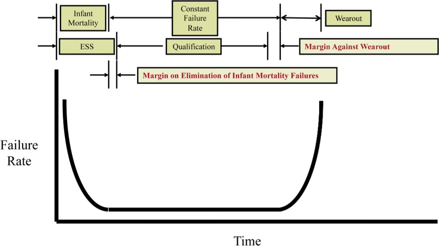
The “constant failure rate” portion of the curve is the section after infant mortality defects have been eliminated. But before wearout begins to occur, failures are “random.” This is the period for which constant failure rate statistical prediction techniques (MIL-HDBK-217, VITA 51.1, and so on) have some validity.
The “wearout” portion of the curve is the last section where the failure rate increases substantially due to metal fatigue. Durability/endurance/life verification (analysis and/or test) during item qualification is intended to demonstrate that wearout will not occur during the planned life of the item.
Limitations of the reliability prediction process
MIL-HDBK-217 (as do most similar analysis techniques) relies on a number of assumptions, two of which are germane here:
- Infant mortality failures have been eliminated by good process control, or screened out by an effective ESS program that consumes a relatively small percentage of “demonstrated life.”
- The period of performance after ESS is within the “demonstrated life” of the item, so that “wearout” failures will not occur.
Selecting the applicable MIL-HDBK-217 “PiE-factor” (the adjustment factor for severity of environment) will not remotely compensate for the failure to adequately specify durability environments. The “PiE-factor” ratios assume, as does everything in the MIL-HDBK-217 methodology, that durability has been demonstrated and that the item is in the “constant failure rate” portion of the bathtub curve. They do not account for limited life due to “wearout.”
The salient contributors to equipment endurance/durability/life environments are vibration and temperature cycling. The deleterious effects of these environments are widely understood, and have been thoroughly investigated in a number of venues.
The Bolton Memorandum and ANSI/GEIA-STD-009 both confirm the need to address the fatigue aspects of both thermal and vibration fatigue. Ideally the durability environments should be derived from the item’s planned usage.
The temperature cycling fatigue environment is usually caused by the combination of diurnal nighttime low temperatures and the maximum temperature achieved at each potential failure site (solder joint, component lead, and so on) as a result of diurnal daytime high temperatures, cooling system performance, operational cycles, and equipment power on-off cycles.
Experience on programs where durability fatigue analyses have been conducted and validated shows that the temperature cycling fatigue contribution is typically 80 to 90 percent of the total. This is true even for platforms with relatively severe vibration environments.
Vibration and temperature cycling environments are orthogonal to each other
Circuit Card Assembly (CCA) vibration fatigue (primarily component leads and solder joints) is typically due to the flexure perpendicular to the plane of the CCA: As the CCA flexes repeatedly, the strains imposed on the component leads and solder joints lead to the accumulation of fatigue damage.
CCA temperature cycling fatigue (again, primarily component leads and solder joints) is due to Coefficient of Thermal Expansion (CTE) mismatch between the component and the CCA in the plane of the CCA: As the CCA goes through repeated thermal cycles, the strains imposed on the component leads and solder joints lead to the accumulation of fatigue damage.
Changes to improve performance in one endurance/durability/life environment can degrade performance in the other. For example, stiffening the card to improve vibration performance could degrade performance in temperature cycling. It follows that long life in one durability environment does not imply any life in the other.
Environmental stress screening
As previously noted, the intent of ESS is to precipitate infant mortality (latent manufacturing) flaws so that they can be repaired, and the fielded item will be at the beginning of the flat portion of the bathtub curve.
A longstanding industry “rule of thumb” holds that Power Spectral Density (PSD) levels below 0.04 g2/Hz are insufficient to precipitate flaws.
Another industry rule of thumb holds that ESS should not consume more than 5 percent of the demonstrated endurance/durability/life of the item. This is to increase the probability that the item remains on the flat portion of the bathtub curve for its planned useful life.
Table 1 makes use of the equation from MIL-HDBK-810F, Paragraph 2.2 Fatigue Relationship, to determine the percentage of demonstrated durability life consumed by ESS on a hypothetical program. For this hypothetical program, ESS is performed for 10 minutes at 0.04 g2/Hz. Durability vibration testing is conducted for five hours (300 minutes) at different levels depending on the item installation zone. In this hypothetical case, conducting ESS for items installed in installation zones with PSDs of 0.04 g2/Hz or higher might make sense, assuming that the items have infant mortality defects. For items installed in the zones with lower PSDs, the conduct of ESS is non-value added, meaning that the field/durability vibration level is too low to precipitate any infant mortality defects. It is also deleterious to the items’ reliability, as an excessive portion of demonstrated durability vibration life is consumed.
Table 1: The equation from MIL-HDBK-810F, Paragraph 2.2 Fatigue Relationship, is used to determine the percentage of demonstrated durability life consumed by ESS on a hypothetical program.
(Click graphic to zoom by 1.9x)
|
|

If the unit had to repeat (there is no limit to how many times this could happen) the last five minutes of vibration after failure correction, then well over 100 percent of demonstrated useful life would have been consumed.
Again, for the hypothetical program, an endurance/durability/life temperature cycling requirement is not specified. Even assuming that there are no repeated cycles following correction of a failure, at least 100 percent of demonstrated useful life has been consumed when ESS is completed. In the absence of an endurance/durability/life temperature cycling requirement, one pass through ESS is all that is included in the demonstrated temperature cycling durability life. If there are repeated ESS cycles, then the situation would be considerably worse.
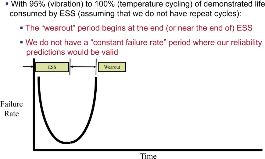
In this case, the bathtub curve is shown in Figure 2. The actual item might be better than the requirements, but there would be no evidence or data to show that this is the case. The flat portion of the bathtub curve, where our reliability predictions have some validity, does not exist. The inherent reliability of the unit has been degraded by the fatigue damage it has accumulated. In the case of vibration, this was done in the attempt to eliminate latent defects that the field level is too low to precipitate.
Figure 2: This bathtub curve shows 95 to 100 percent of demonstrated life consumed by ESS.
(Click graphic to zoom by 1.8x)
|
|
ESS is an attempt to “inspect in” quality for low production rate equipment. Defects in high production rate equipment can be reduced or eliminated by the application of statistical process control and automation. High production rate equipment is far more likely to be COTS than custom military specification design. It follows that COTS is far more likely to be defect free than custom military specification design.
How program/equipment managers can avoid these pitfalls
One way to decompose reliability is into two questions. First, is the item inherently robust enough? (Endurance/durability/life environments address this.) Second, is the item defect free? Boeing has experience flying COTS items such as Ricoh printers, Sony satellite dish receivers, and HP servers on military-derivative aircraft without conducting ESS. In this relatively benign environment of commercial aircraft converted to a military application, COTS items have proven considerably more reliable than the military specification Government Furnished Equipment (GFE). These COTS items are clearly not robust enough for severe environment platforms such as fighter aircraft, but their reliable performance on military-derivative aircraft confirms that ESS would be non-value added since field experience has shown these items to be relatively free of infant mortality defects. In addition, given that the items were not designed for flight environments, ESS would be more likely to degrade reliability by consuming an excessive portion of their durability life.
- Durability environments must include vibration and temperature cycling requirements consistent with the planned usage and planned useful life.
- ESS vibration and temperature cycling must be limited, in each case, to some small portion (typically 5 percent) of demonstrated life, including a specified number of allowed repeat/repair cycles.
- Vibration ESS should not be conducted when the durability vibration level is too low to precipitate infant mortality defects.
- ESS should not be conducted on items (typically COTS) shown to be free of infant mortality defects.
The proper application of qualification, ESS, and reliability prediction methods, avoiding the system engineering pitfalls described herein, will minimize total ownership cost while enhancing effectiveness for the warfighter.
James A. Robles is a Boeing Senior Technical Fellow working in electronic packaging disciplines including system architectures, avionics hardware design, mechanical tolerance analysis, thermal and dynamic/vibration analysis, weights/mass properties analysis, design of experiments, environmental analysis and test, reliability, and environmental stress screening. He leads the ITAA working group for EIA-933 Standard for Preparing a COTS Assembly Management Plan. Additionally, James is the Boeing Focal for VITA, developing open standards for next-generation COTS assemblies for military/aerospace applications. He can be reached at [email protected].
The Boeing Company 253-657-5663 www.boeing.com
A longer version of this article is available at www.mil-embedded.com/articles/id/?3839.