Case study: OpenVPX systems help deliver UAV program quickly
StoryJune 21, 2010

Anne Mascarin
Mercury Systems
Greg Rocco
Mercury Systems
The OpenVPX standard's interoperability and Quick Reaction Capability (QRC) support features allow it to quickly resolve issues and reduce time to integration.
Today in the embedded systems community, product development speed and efficiency are competitive weapons. In many of the targeted applications for OpenVPX (VITA 65), bringing reliable, high-performance technologies to market successfully can have a very significant impact. One area clearly supported by OpenVPX is the Quick Reaction Capability (QRC) obligation, where the development and deployment cycles demanded are significantly reduced to achieve critical program needs. The following defense application case study illustrates how OpenVPX meets those needs. This example is a combination of actual experiences, and what is expected to be a typical engagement. Where possible, time savings and other benefits of the OpenVPX specification are included.
Development blast-off: The requirements
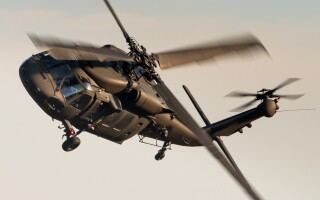
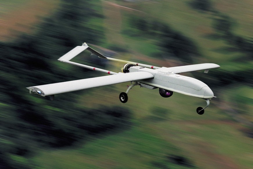
A small UAV (see Figure 1) required an airborne image and signal processor to process, exploit, and disseminate large amounts of multi-sensor data. As a technical refresh effort, the requirements were to design, lab test, and deploy the processor for initial flight-testing within 10 months. Achieving Size, Weight, and Power (SWaP) and QRC schedule requirements was crucial to winning and executing this contractual commitment. Accordingly, an initial flight-test date was fixed and a monetary penalty identified in the contract for missing the flight-test date. Commercial items and open standards components were mandated as a way to reduce time-to-market and total cost of ownership requirements; considering these items and components also necessitated that only a multi-vendor, integrated development approach would be feasible to meet the aggressive time schedule.
Figure 1: A small UAV required an airborne image and signal processor to process, exploit, and disseminate large amounts of multi-sensor data in the described case study.
(Click graphic to zoom by 1.9x)
|
|
Preliminary research outcomes
A requirements creation team performed initial analysis to evaluate a potential solution for architecture, SWaP, data flow, and processing requirements. VXS, VME64x, and OpenVPX were all considered. 6U VXS and VME64x were rejected because they were too large and because they did not have enough high-speed signal pins. (VME64x does not have any.) The outcome of this analysis resulted in the determination that 3U OpenVPX would provide the best fit.
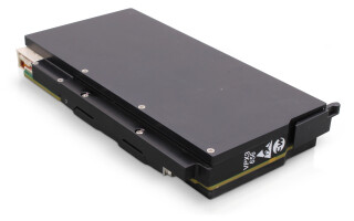
An existing Mercury VITA Radio Transport standard (VITA 49) XMC module was integrated on a Mercury 3U OpenVPX FPGA processing card. Mercury 3U OpenVPX modules were used for the processing. A 3U OpenVPX SATA Storage Module was used for non-volatile storage, and a customer-provided custom XMC was used to interface to other subsystems including status/control of the sensor. The custom XMC was put on a third-party 3U OpenVPX XMC carrier. The XMC carrier used a VITA 46.9 mapping to get the I/O to the backplane and a PCIe Expansion Plane connection to connect to a Processing Module.
Because of the interoperability and QRC needs required in the multi-vendor integrated subsystem, an OpenVPX subsystem was chosen by the team and specified in the solution requirements document. The RFP generation team estimated that the RFP generation process required 25 to 50 percent less time as compared to similar efforts, because OpenVPX assured a common frame of reference and clarity of definitions. RFP generation time also decreased because the OpenVPX frame of reference improved and speeded communications within the requirements creation team.
The choice: OpenVPX modules and more
Using the OpenVPX system architecture specification as a tool, the system design team quickly determined that a 3U 8-payload and 2-switch slot OpenVPX air-cooled chassis would be suitable for development and a 6-slot chassis would be used for deployment. The development system is one of the standard 3U development topologies defined in the OpenVPX specification (Figure 2).
Figure 2: Backplane profile BKP3-CEN10-15.2.4-n is shown here. Appropriate payload and switch module profiles were chosen from the specification as described in our case study.
(Click graphic to zoom by 1.3x)
|
|

The chassis topology and power definitions were chosen from the specification selection, which was clearly defined by table-driven part numbers. User-defined signals were used by the VITA 46.9 mappings for the carrier of the customer XMC and interfaces on some of the other 3U modules for sensor status, sensor control, and interfaces to other subsystems. In the development environment, these user-defined signals were connected via a combination of Rear Transition Modules (RTMs) and cables. Because the OpenVPX specification limits requirements investigations to a small number of well-defined choices – where pin assignments, placements and protocols are clearly defined – the system design team estimated that the design effort required approximately 50 percent less time to develop than similar efforts sans OpenVPX.
The critical information for each module, backplane, and chassis was then defined and inserted into the necessary RFQs for required third-party elements. All RFQs referenced the VITA 65/OpenVPX systems specification as the guiding reference document. Multiple RFQs were issued to the chosen suppliers for a 30-day return cycle.
Because all vendors were working from the OpenVPX specification, a common frame of reference was available, as mentioned: identifying the most relevant architecture and design information greatly reduced board, chassis, and backplane suppliers’ response time. Also, from an initial review of a potential supplier’s data sheets, the integrator was able to assess that many OpenVPX-specified products existed off-the-shelf; thus, the module and chassis profiles chosen came from an ecosystem of supplier products requiring little or no custom effort. Therefore, early on, these OpenVPX specification enablers provided a clear risk-reduction path toward achieving QRC goals. See Figure 2 as an example of the 3U backplane profile from the OpenVPX specification.
Ready, set, go: Integration
Consequently, only 90 days after the vendors were chosen, the initial OpenVPX backplane and third-party supplier modules were expedited to the development facility and made ready for initial integration.[1] Several minor interoperability issues were quickly resolved during hardware integration and software development, and further test efforts proceeded to achieve QRC flight-test goals.
As an example of a typical problem that can occur during integration, there was a problem with a cable used to route some high-speed serial pairs from the backside of the slot with the carrier of the custom XMC. These high-speed pairs are used to interface to another subsystem. Initially the cable was wired as if it were connecting to high-speed pairs from the Expansion Plane instead of from an XMC carrier. VITA 46.9 has high-speed pairs wired differently from methods used for fabric connections such as the Expansion Plane and Data Plane ports. This difference was missed by an engineer on the team who was new to this ecosystem. Fortunately, the problem was caught early, when it was just a cable in a development system and not the custom backplane for the deployed system.
According to the integration team, the OpenVPX specification quickly resolved integration conflicts by mitigating rework cycles, minimizing “finger pointing” between development and integration groups, and reducing interoperability issues, which led to a 50 percent reduction in integration time.[2]
Anne Mascarin is a product marketing manager at Mercury Computer Systems. She can be contacted at [email protected].
Greg Rocco is a systems consulting engineer at Mercury Computer Systems. He is the lead editor of the OpenVPX System Specification. He can be reached at [email protected].
[1] The deployed backplane and conduction-cooled chassis were developed in parallel with the system software. With the deployed chassis, the backplane items that were cabled via RTMs in the development system were routed in the backplane.
[2] The estimates cited are based on the demonstrated experience of Mercury’s OpenVPX engineering team while working with customers. Other teams, and the industry as a whole, can reap similar benefits by embracing the potential of OpenVPX.