Movers and shakers: Simultaneous multiaxis testing tops sequential axis methods
StoryJune 17, 2009

Wayne Tustin
Equipment Reliability Institute
Simultaneous multiaxis vibration testing is shaking up the testing world - and beating out the more common sequential axis shaking method.
Most engineers would readily agree that “real-world” vibration is likely to be multi-axis. They would also agree that aircraft, missiles, rockets, land vehicles, and ships must simultaneously shake all onboard electronic and other hardware in multiple axes X, Y, and Z. In their own experience driving an automobile or riding in an airplane, bus, or train, they have felt multiaxis inputs. When they are first exposed to military and other vibration test procedures, most engineers are surprised by the ancient laboratory practice of sequential or single-axis-at-a-time shaking (see Sidebar 1).
However, with the appearance of new Test Method 527 on Multi Exciter Testing – which appears in the latest “G” revision to the venerable Military Standard 810 Department of Defense Test Method Standard for Environmental Engineering Considerations – engineers will at last find some incentive for simultaneous (Figure 1) rather than sequential multiaxis shaking of military embedded systems.
Figure 1: An array of three electrodynamic shakers simultaneously vibrates test items north-south, east-west, and up-down. (Courtesy Spectrum Technologies, Inc., Redford, Michigan)
While this discussion emphasizes automobiles and automotive testing, mainly because of likely reader familiarity with automobiles, the concepts presented also apply to testing a wide variety of military and commercial land, sea, and air vehicles. Single-axis-at-a-time or sequential shaking is reviewed, and the benefits of multiaxis shaking – servohydraulically at relatively low test frequencies and electrodynamically at higher test frequencies – are explored. These benefits apply not only to the usual “frequency domain” testing in terms of power spectral density but also to “time domain” testing in terms of force or acceleration versus time.
Sidebar 1: Sequential axis testing began in the 1950s and unfortunately is still used today despite its limitations
|
|

Servohydraulic single and multiaxis shaking
Mechanical shakers were stroke and frequency limited. Thus, the need for several-inch strokes shaking frequencies prompted the development of servohydraulic (electrically valved high-pressure, oil-driven) shakers, various-sized actuators for transportation vibration testing of cartons or pallet loads of packaged goods. The frequency range is somewhat limited; however, servohydraulic shakers are rarely used above 500 Hz. Many are never used above 200 Hz. But automotive test engineers have long used four such actuators to vertically shake a test platform that represents a railcar or a motor truck carrying new cars from factories to dealerships.
Pioneering users of such systems were not satisfied with single-axis shaking, though. They could not replicate in the lab all the damage (such as assemblies loosening and parts losses) that occurred when shipping completed automobiles. Fortunately, a few engineers recognized that they could vary the phase between the electrical signals driving the servovalves on the four shakers (see Sidebar 2). Their test platforms could then be made to roll and pitch as well as shake vertically. Adding more shakers (lateral and fore-and-aft shakers) enabled two more translations as well as yaw: six platform motions. Such a multiaxis vibration laboratory test platform can represent a familiar sight: special-purpose railroad cars carrying completed automobiles from factory to dealership. The lab can identify potential “in transit” failures, leading to automobile redesign and/or manufacturing changes such as stiffening of suspension attachment bushings.
So what about road and off-road terrain inputs to vehicles in use? For these tests, land vehicle developers shake the individual wheels. Typically, a total of 12 servohydraulic shakers is used. Note the vast amount of lab area required for such testing. One manufacturer of servohydraulic shakers has put six such shakers inside a hollow steel cube, causing the cube to simultaneously shake in six axes. An automobile resting on four such cubes uses little lab space. Or one such cube can multiaxis shake a number of automotive assemblies and/or sections of automobiles in which electronics are embedded.
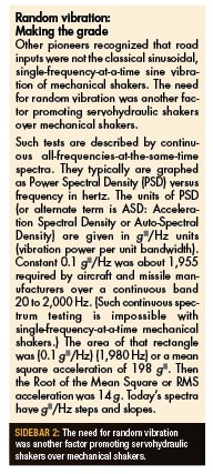
Sidebar 2: The need for random vibration was another factor promoting servohydraulic shakers over mechanical shakers
|
|
Military electrodynamic simultaneous multiaxis shaking
In order to shake microelectronic and other small assemblies at higher test frequencies, typically 1,000 or 2,000 Hz, electrodynamic (alternating current in coil located in strong magnetic field – similar to a loudspeaker) shakers such as those in Figure 1 had to be developed.
Common test lab interpretation of Military Standard 810 Test Method 514 has been sequential single-axis-at-a-time vibration. In most testing labs, engineers have never seen or even considered simultaneous multiaxis shaking. However, there have been several incidents in which military hardware has failed in the field, but those failures could not be duplicated in the laboratory. Very few military labs have obtained funding to add two more electrodynamic shakers:
- The U.S. Army at Adelphi, Maryland and at White Sands Proving Ground, New Mexico
- The U.S. Navy at Keyport, Washington
- The U.S. Air Force near Ogden, Utah
Consequently, axes X, Y, and Z can now be excited simultaneously. In some of these situations, the hidden failure modes have appeared. That is the greatest motivation for Military Standard 810G’s new Test Method 527 on Multi Exciter Testing.
The other motivation is economic: faster, one test instead of three, and one attachment fixture instead of three to be designed and fabricated. Interestingly, automotive multiaxis shaking is common practice in the test labs of Japanese automobile manufacturers. Several Japanese shaker manufacturers offer multiple electro-dynamic shaker arrays somewhat similar to Figure 1. They differ in their manner of connecting three shakers to a common load, Figure 2.
Figure 2: Payload adapter accepts mutually perpendicular inputs from three electrodynamic shakers. (Courtesy IMV Corporation, Osaka, Japan)
Only one independent environmental testing laboratory in North America provides simultaneous multiaxis vibration testing to 2,000 Hz: Spectrum Technologies, Inc. of Redford, Michigan. STI offers these services to military, automotive, and other hardware makers. Occasional training held there uses the system shown in Figure 1 to demonstrate simultaneous multiaxis vibration testing.
Time Domain Replication: An alternative to continuous spectrum testing
Military and other testing standards here and abroad commonly tell testers to gather and use their own data rather than use the provided spectra. Accordingly, some automotive STI clients gather their own over-the-road or off-road vibration data. They might mount “triaxial” accelerometers or they might appropriately mount three single-axis accelerometers at their locations of interest. They gather acceleration data and save it in the time domain, ready for Time Domain Replication (TDR) testing.
Under the previously described continuous spectrum testing, their “time domain” data (millivolts versus time) would have been time-averaged, then Fourier transformed into a spectrum in the frequency domain. Spectra would have been keyboard input by operators into digital shaker controllers. Digital-to-analog conversion would have been needed to develop a signal for each power amplifier to drive its electro-dynamic shaker. Each shaker’s motion would have spectrally matched its requirement. Unfortunately, that time averaging greatly reduces shaker reproduction of brief severe events such as the occasional highway bump or chuckhole. Those brief events were always under-represented in shaker motion.
TDR avoids that averaging and is believed to better reproduce shock events. The three acceleration signals remain in the time domain and pass without time averaging to each power amplifier and each shaker. Another term for TDR is RoadLoad signal replication.
The future of simultaneous multiaxis shaking
In coming years, more and more test labs will “go simultaneous multiaxis,” though there will be complaints about the required investment. Back in the 1950s, similar complaints were voiced about users’ first electrodynamic shaker purchase. Once installed and used, that first shaker found so many weaknesses in the products tested that the shaker was soon used 24 hours per day. Then additional shakers were quickly purchased. That pattern will repeat with simultaneous multiaxis shaking.
Wayne Tustin is founder and president of the Equipment Reliability Institute in Santa Barbara, California, a specialized engineering school.
Equipment Reliability Institute 805-564-1260 www.equipment-reliability.com