For New Space satellites, radiation tolerance means new design hurdle
StoryJune 09, 2023

Salah Ben Doua
Vicor Corporation
Ken Coffman
Vicor Corporation

While semiconductor device selection is at the heart of developing radiation-tolerant power systems for space applications, it is just one of many design strategies that can be deployed at the component and circuit levels. There are basic strategies to explore, plus the multiple benefits of soft switching in radiation-tolerant power systems.
When it comes to building satellite power electronic systems that operate reliably in space, engineers have a plethora of challenges to overcome. The absence of Earth’s magnetic field makes it difficult for satellites to deflect high-energy particles. Moreover, without the Earth’s protective atmospheric shield, space systems are also vulnerable to greater levels of wave and particle radiation that can trigger component malfunctions and even compromise the system itself. Another hurdle: heat dissipation, as convection cooling does not work in space, thereby limiting the removal of heat through conduction to a radiating surface.
Against this backdrop, so-called New Space applications have shown they are able to incorporate radiation-“tolerant” components as opposed to more robust radiation-“hardened” circuitry, for example, by lowering the bar for total ionizing dose (TID) exposure. However, radiation damage is cumulative, so the length of the mission is a factor that determines the intensity of radiation, as does its orbital position.
Mitigating the effects of particle radiation
Wave radiation includes rays and electromagnetic waves. Generally, wave radiation has properties similar to optics, including reflection, absorption, refraction, and diffusion. However, radiation wavelengths in space extend above and below the visible light spectrum. Radiation below visibility includes microwaves and radio frequencies (RF), while radiation above visibility includes ultraviolet, X, and gamma rays. In Figure 1, note the wavelengths and associated energies, which are key parameters for measuring radiation exposure.
.jpg)
[Figure 1 ǀ A diagram shows the radiation spectrum.]
Wave and particle radiation are not really two separate things, but the effects on electronic systems are different. Individual particles have little mass, but can be accelerated to high velocities. They can also carry charges, which are generally positive when negative-charge electrons are stripped from atomic orbits.
We see physical damage from particle radiation, particularly to semiconductor crystal lattices; this damage is permanent and/or cumulative. We can see temporary upsets where electrons are dragged into depletion regions and make a nonconducting region conduct. We also see malfunctions when positive ions replace doping atoms in a crystal matrix, which can make a semiconductor conduct when or where it shouldn’t, resulting in permanent damage to equipment.
An added factor in the vacuum of space is that the useful convection used for terrestrial cooling does not work. Conduction works for spreading thermal energy, but eventually, excess heat must be radiated into cold space. A complicating factor is that surfaces exposed to the sun will get very hot, on the order of 250 ˚F (120 ˚C), while shaded surfaces will be very cold, around -238 ˚F (-150 ˚C).
Building robust rad-tolerant power electronics
Even in today’s fast-paced New Space business environment, costs to launch and replace dead satellites are substantial, so care in design is important.
How is this done? There is no one answer; solutions for creating robust space electronic systems are multifaceted.
First, components are selected for radiation tolerance. Some state-of-the-art semiconductor process nodes have improved radiation performance. Bipolar semiconductors can be selected for their displacement damage ratings. Wide-bandgap (gallium nitride or GaN) FETs [field-effect transistors] with inherent radiation tolerance can be selected. Some parts, like certain epoxies and aluminum electrolytic capacitors that outgas in a vacuum, are simply inappropriate for use in space environments.
Physical redundancy is also important to ensure that, if one system fails, another can take over. In some designs, three systems operate in parallel: If one disagrees with the other two, then its output can be ignored. Sometimes there are four redundant systems and one spare is swapped in if a system fails. Even with these safeguards, radiation-tolerant design requirements restrict the selection of components. The addition of performance monitors, safety mechanisms, power disconnects, and reset circuitry must not exceed the efficiency, size, and weight requirements of the final solution.
The impact of topology selection and switching mode
Regardless of design strategies and power-supply topologies, space electronic systems must be analyzed, simulated, and tested for environmental and radiation performance.
Balancing design tradeoffs by choosing an appropriate power system architecture is important. Topology and switching modes like soft switching (versus hard-switched power converters) can make a system less sensitive to parasitic effects like ringing, which can increase voltage stress on switching components.
As one example of the importance of topology selection in a new space design, the switching mode affects all the key specifications of power-conversion implementations, including power density, efficiency, transient response, output ripple, electromagnetic interference (EMI) emissions, and cost.
Dominant switching-loss terms are attributable to the turn-on behavior of a power train’s high-side MOSFET [metal-oxide semiconductor field-effect transistor] via gate-charge requirements and drain-to-source capacitance. Switching losses increase with, and thus limit, switching frequency. Body-diode conduction losses detract further from power-conversion efficiency in hard-switched converters. Though GaN FETs do not have a physical body diode, they do have a reverse conduction mode clamping at several volts. This setup makes the GaN dead-time conduction period challenging to manage.
In a synchronous, hard-switched buck topology, the high-side FET turns on when it has the maximum voltage across it (Figure 2) and it conducts its maximum current during the turn-on portion of the operating cycle. Power losses in the high-side switch, therefore, are at a maximum during the off-to-on transition. The larger the input voltage, the higher the power loss, so converters in high voltage-ratio applications (for example, 28 V to 3.3 V) tend to deliver poorer efficiency than the same converters in circuits demanding lower conversion ratios (for example, 5 V to 2.5 V).
.jpg)
[Figure 2 ǀ Shown: Topology parasitics]
The benefits of soft switching
The alternative, soft switching, significantly reduces these switching losses. Soft-switching techniques require more complex control circuits because the switch timing must be coordinated with the switched waveform.
One example of soft switching is the zero-voltage switching (ZVS) technique, which improves conversion efficiency across a range of power topologies. As the name suggests, ZVS switches the high-side FET on when the voltage across the switch is at or near zero (Figure 3a). This breaks the link between power losses and the voltage conversion ratio during the high-side FET’s turn-on interval. Operation of a clamp switch with the ZVS technique enables the converter to store a small amount of energy in the output inductor when both high-side and low-side switches are off. The converter uses this otherwise-wasted energy to discharge the high-side FET’s output capacitance and charge the synchronous FET’s output parasitic.
Taking the FET’s output capacitance out of the switch’s turn-on behavior desensitizes FET selection with regard to gate-drain capacitance (CGD) and enables designers to focus on on-state channel resistance instead of having to concentrate on traditional figures of merit such as the product of channel resistance and gate capacitance.
This method of driving the high-side FET during turn-on avoids exciting the switch’s parasitic inductance and capacitance, which tend to resonate and induces large voltage spikes and ringing in hard-switched topologies (Figure 3b). By eliminating the spikes and preventing the ringing (Figure 3a), ZVS removes another power-loss term and eliminates a source of EMI emission.
Eliminating the voltage spikes from the switching behavior also enable designers to select lower-voltage FETs with lower drain source on-resistance [RDS(on)], improving the efficiency.
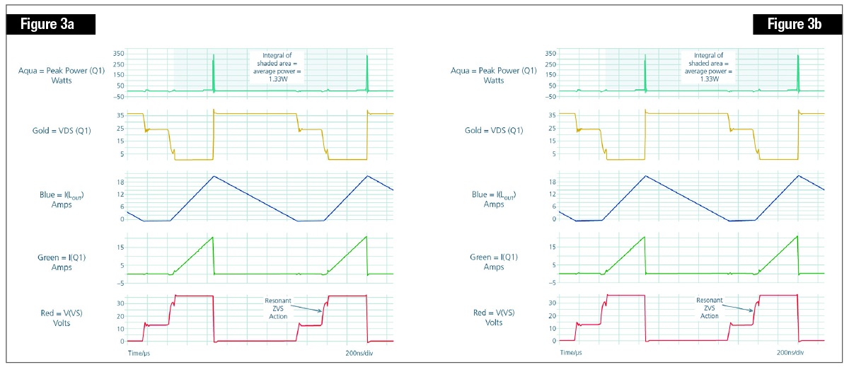
[Figure 3 ǀ Hard-switching versus soft-switching waveforms are shown.]
Soft switching is extremely versatile. For example, Vicor uses soft-switching techniques in its radiation-tolerant power module solutions for powering high-performance communication ASICs [application-specific integrated circuits] (Figure 4) dedicated to MEO and LEO [medium-Earth orbit and low-Earth orbit] satellite applications. The system modules use ZVS buck-boost topology for the PRM and ZVS and ZCS sine amplitude converters (SACs) for both the BCM and the VTM.
The small size of the VTM enables placement as close as possible to the ASIC. Optimizing the power distribution network (PDN) is critical when dealing with the high currents of modern ASICs, FPGAs [field-programmable gate arrays], CPUs [central processing units], and GPUs [graphics processing units]. Vicor modules combine soft-switching solutions, rad-tolerant active components, and automotive-qualified passive components.
To mitigate the single-event function-interrupt (SEFI), all radiation-tolerant modules include completely redundant power trains operating in parallel. If one power train is upset due to a single event, its protection circuits force a power-off reset. During the reset interval, the redundant power train carries the full load and after the reset both power trains operate in parallel again.

[Figure 4 ǀ Shown: High-power resonant (ZVS and ZCS) topology modules.]
The bottom line: radiation-tolerant electronic systems are hard to design.
Salah Ben Doua has 30 years of experience in the field of power design and has been supporting Vicor for more than 20 years, providing expertise and advice in the development of DC/DC and AC/DC power systems in a multitude of areas, including aerospace and defense, industrial, rail, lighting, and communications. Salah received a Ph.D. from the National Polytechnic Institute of Toulouse (France), specializing in power conversion. Author, publisher, and engineer Ken Coffman holds a BS degree in electrical engineering technology from Cogswell College North, is the co-author of six technology patents, and has many years of power-supply design experience. Located in the Phoenix, Arizona area, he is assigned to Vicor’s New Space Initiative. Readers can reach Ken at [email protected] and he is easy to find on LinkedIn.
Vicor • https://www.vicorpower.com/


Featured Companies
Vicor Corporation
Andover, MA