Dealing with a real-world thermal triple threat
StoryJuly 25, 2022

Kevin Griffin
Atrenne Computing Solutions
As increasing numbers of embedded systems are deployed on small platforms, thermal overdesign – or designing for a physically impossible worst case of simultaneous maximums – is becoming a significant issue. It can be addressed, without compromising system viability, by using a real-world focus to define combinations of thermal triple-threat specifications. Engineers can then use software simulations for each combination of specs in an iterative fashion, modifying design parameters until acceptable thermal performance is achieved for all combinations.
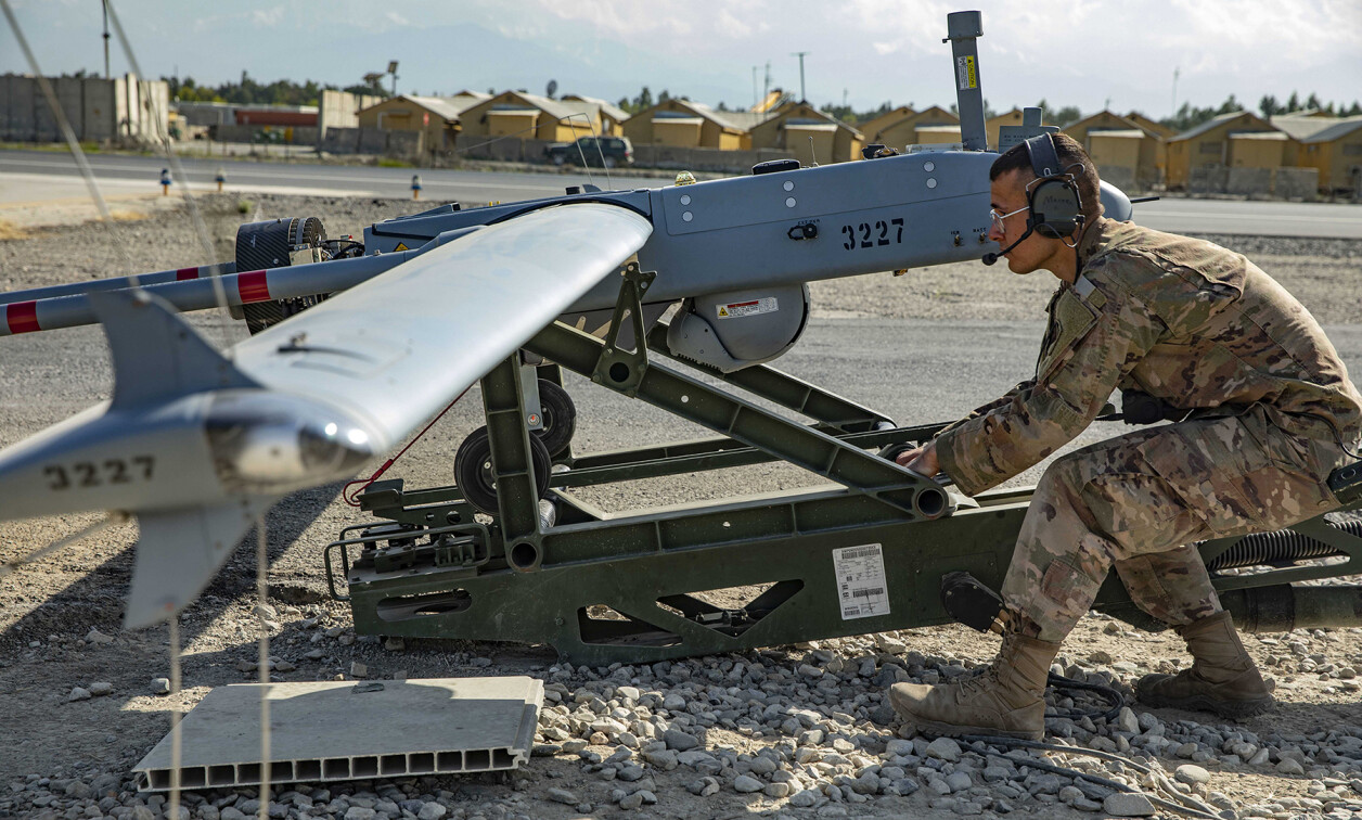
On an abandoned parking lot in the tropics, three soldiers prepare a small UAV [unmanned aerial vehicle] for reconnaissance critical to their unit’s mission. The temperature on the blacktop is over 120 °F and the CPU controlling the UAV’s imaging system is running through the start-up procedure; the soldiers can hear the system’s fans moving the hot air over hotter electronics.
System start-up goes smoothly, the UAV uses its launcher to take off, and the soldiers retreat to a shaded area where they can monitor and control the flight. As the UAV climbs above 5,000 feet the air becomes cool and the fans slow down, even though multiple GPUs are now starting to process imaging data. The climb continues to above 10,000 feet, where it is so cold the fans turn off, even though the air is thin and all components in the imaging system are operating at full capacity.
The UAV flies for several hours, collecting detailed information across a broad swath of disputed terrain. Having what they need, the soldiers direct the UAV to return. During the descent the system shuts off all but control functions and, as it touches down on the hot macadam, the fans restart. The UAV and its imaging system will be ready for another mission tomorrow if needed.
The thermal triple threat
As this scenario demonstrates, embedded systems routinely deal with a thermal triple threat: heat generated by system electronics, ambient air temperature, and altitude – or more specifically, the air density determined by altitude.
Virtually every deployable embedded system has system requirements defining a set of triple-threat specifications that must be met during operation. While the maximum heat load varies greatly between systems (based mostly on the type and number of processors), maximum ambient temperature is frequently set at 71 °C (160 °F) and maximum altitude often at 30,000 feet.
There is nothing inherently wrong with these requirements; they represent maximums that could be encountered during real world operations. However, there is a departure from the real world when requirements mandate reliable system operation under a condition of all three maximums simultaneously. The most obvious example of this fallacy is that in the real world the ambient temperature at 30,000 feet will never be anywhere close to 71 °C – at that altitude, it is extremely cold.
Designing for real-world extremes
Unfortunately, many requirements documents still do exactly that, defining a physically impossible worst case of simultaneous maximums, perhaps justifying it as a conservative engineering approach. This, of course, inevitably leads to the overdesign of cooling components – more fans, bigger fans, more heat sinks, and more thermal-conduction material.
In the past, the cooling overdesign issue has not been a huge problem. For an embedded system in a large, manned aircraft, a few extra fans drawing a few extra watts, or a few hundred grams of unneeded material, are not a big burden. A big platform can easily support the extra weight and power draw.
But for small platforms, like today’s tactical UAVs, cooling overdesign will compromise mission capability. Every fraction of a kilogram and every watt make a difference in how long a UAV can stay on station and gather information.
The clear solution is specifying and designing systems based on a real-world thermal triple threat. The relationship between maximum ambient air temperatures to altitude is well understood. Specifications should incorporate that relationship, so that the specifications for altitude and ambient temperature can then be established as a series of steps, X° at sea level, Y° at 5,000 feet, etc.
A real-world understanding of how the system will be deployed is also important. If the platform can’t operate above 18,000 feet, why put 30,000 feet in the system specification?
Understanding the details of the embedded system’s operation can then be used to determine maximum power draw and heat generation by the electronics in a way that fits with the temperature-altitude steps. Not all the processors in a system run at full power all the time simultaneously. They certainly don’t all run at full power simultaneously in an airborne system while it is on the runway. What is the real-world worst-case power draw, and for how long, at each altitude step?
Using simulation scenarios
A highly effective design approach for the thermal triple threat uses sets of software-simulation scenarios with realistic variations of heat load, altitude, and ambient temperature. A typical simulation effort will define around eight combinations of the triple-threat parameters. Engineers can then iterate through these scenarios, modifying cooling design parameters and rerunning simulations until the simulated system shows effective cooling for all combinations. At that point, the design team can be confident the system will perform reliably in any environment it might actually encounter.
Today's thermal simulation software (example, Figure 1) is flexible and comprehensive. For air-cooled systems, computational fluid dynamics models are normally used, while for conduction cooling there are direct thermal-transfer representations. For complex thermal designs, both types of simulations may be used to model appropriate parts of the system.

[Figure 1 | Autodesk CFD 2019 software simulations produce detailed thermal images for complex thermal designs.]
Ideally, the simulation-based design approach would start out with sets of triple threat specifications defined by a real-world focus. In practice, the simulations are often used by thermal designers to show systems engineers how weight and power demands can be reduced, relative to an over design driven by simultaneous maximums. The result is to ”negotiate“ a set of scenarios representing conditions expected in the real world and to use those as the design targets. Unfortunately, this negotiation occurs during the product design cycle and adds to the development time; things would be more straightforward if the sets of real-world scenarios were in the initial specification document.
A word on wedgelock temperatures
Many conduction-cooled systems have an additional parameter – wedgelock temperature – added to the triple-threat specs, usually set at 85 °C. The expectation is that processor-die temperatures on attached boards will remain below their maximums if the wedgelock spec is not exceeded; the board designers must do the simulations or testing to assure that is true.
As with the triple-threat specs, the specified maximum wedgelock temperature should be examined with a real-world view. Under what set of operating conditions would the attached board draw enough power to reach that maximum? What are the altitude and ambient air temperatures associated with those board operating conditions? Combining real world wedgelock temps with sets of triple threat specs will avoid overdesigns that add unnecessary weight in conduction-cooling material.

Kevin Griffin is a senior mechanical engineer at Atrenne. Kevin has almost four decades of experience in the field of mechanical engineering. Since he began working at Atrenne Computing Solutions in 1984, he has driven his way up through the ranks, progressing from product engineer to systems architect with a focus on electronic packaging for military, industrial, & commercial applications.
Atrenne • https://www.atrenne.com/