Rugged UAV connectors meet the end-to-end challenge for speed and space savings
StoryJuly 27, 2012


The increasing capabilities of UAVs mean heavier demands on signal processing. Embedded computers are evolving to provide high data rates while becoming smaller and lighter, demanding new I/O connectors to prevent bottlenecks in communication.
UAVs have become an important offensive and defensive tool, combining sophisticated surveillance with precision targeting. Since some UAVs are expected to remain aloft for upwards of 36 hours, Size, Weight, and Power (SWaP) are critical issues that affect component selection. At the same time, the signal processing load is steadily increasing to keep pace with advanced imaging, targeting, and controls. These two factors – SWaP and high-performance computing needs – are leading designers to create systems with both higher bandwidth and smaller form factors. This evolved concept in system design has implications for the entire connectivity chain, inside the box and box-to-box.
While VITA 46 (VPX) is probably the most widely used state-of-the-art computing platform for defense and aerospace applications, industry is looking to the next generation of Small Form Factor (SFF) systems. 6U systems are giving way to 3U systems – and even smaller form factors are under investigation by VITA 73, 74, and 75 committees.
The challenge isn’t simply size and speed, but robust connector designs capable of withstanding shock, vibration, temperature extremes, and potential exposure to fuels and other environmental challenges found in aerospace applications such as UAVs.
For example, a commercial backplane connector is typically designed to withstand random vibration of 3 gs over a vibration frequency of 20 to 500 Hz. The military counterpart is tested to higher levels of vibration over a wider frequency range – 11 or 12 gs at 20 to 2,000 Hz. In other testing areas to determine mechanical and environmental ruggedness – such as mechanical or thermal shock or mating cycles – connectors for UAVs and other military applications must withstand much more severe conditions. A closer look inside the box, in an effort to break the I/O bottleneck and design for signal integrity, is important.
Inside the box: Bandwidth, size, ruggedness
As designers look toward next-generation SFF systems, they are also looking for backplane connectors with higher speeds and signal densities than previously available to support the SWaP needs of UAVs. New generations of backplane connectors are providing designers with a smaller footprint at the backplane/daughtercard interface, while supporting 12+ Gbps operation in rugged environments. Such connectors are modular, scalable, and typically compatible with a wide variety of existing optic, RF, and power connectors, thereby expanding the designer’s “in-the-box” arsenal. Thus, they help enable SFF systems.
Breaking the I/O bottleneck
As speeds increase, the input/output connection becomes the bottleneck. Designing connector systems for controlled impedance to maintain signal integrity becomes essential. Since there are many sources of impedance mismatch in a connector – caused by geometric nonuniformity and changes in the dielectric constant – connector interfaces must be designed to minimize crosstalk and reflections from impedance discontinuities that contribute significantly to signal degradations.
Quadrax systems, for example, have supported 100 Mbps and 1 Gbps quite well. But UAV designers today are looking for rugged impedance matched I/O to support 10 GbE, IEEE 1394, USB 3.0, and other fast protocols.
Two common solutions to enable these protocols are to selectively pin an existing 38999 connector in a pattern that minimizes crosstalk between pairs directly by isolation or indirectly by symmetry cancellation or to integrate a commercially available RJ45 modular plug or jack into a rugged Size 19 38999 connector shell. Neither solution is optimal. Military circular connectors such as 38999 were not designed for the match impedance required for high-speed operation, leading to several limitations that include wasted space in selective loading. Proposed approaches use a Size 17 or 10 shell with selective contact loading. While these approaches allow increases in I/O speed, they do not fully meet the return loss requirements of a Cat 6A connector – the industry-standard measure for 10 GbE. Category 6A twisted-pair cable is the industry-standard cable for 10 GbE, and the connector must also meet the ANSI/TIA-568C.2 requirements for Cat 6A hardware. Today’s high-speed requirements in military UAV applications demand connectors with smart signal integrity configurations.
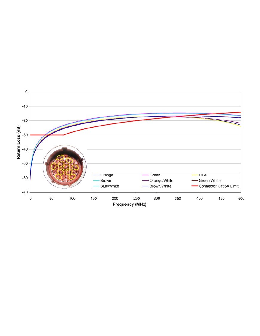
Figure 1 shows return loss measurements for a Size 17 shell tested up to 500 MHz with Cat 6A cable. The pinout pattern is based on an ARINC 664 proposal for 1 Gbps operation and illustrates that, while the pinout can be configured to operate satisfactorily for 1 GbE, it does not meet the return loss requirements for a Cat 6A connector at 10 Gbps.
Return loss is a handy metric for comparing connectors for high-speed use since it directly or indirectly indicates the quality of impedance matching and crosstalk cancellation.
Figure 1: Return loss results for a selectively pinned 38999 connector show that the connector fails to meet Cat 6A requirements at high frequencies.
(Click graphic to zoom)
|
|
Designing for signal integrity
Rather than “force fit” an existing design for 10 Gbps operation, TE Connectivity’s new CeeLok FAS-T connector is an example of how designing a connector for signal integrity can yield both a smaller size and faster speeds up to 10 GbE operation. Achieving both smaller size and faster speeds is critical in UAVs.
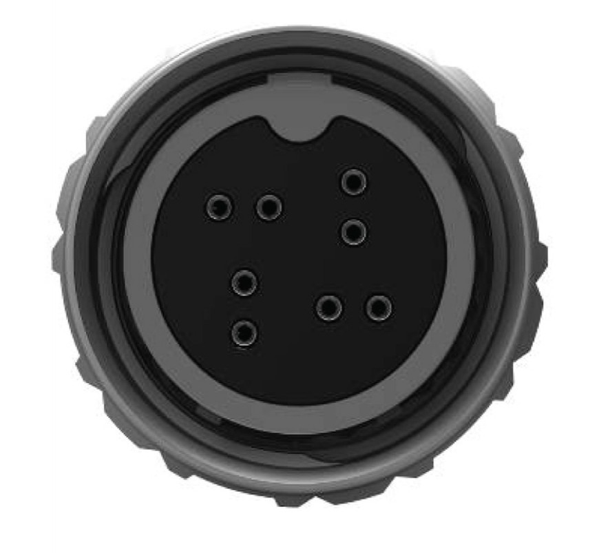
To minimize the effects of crosstalk within the interface, a symmetrical contact pair pattern provides better noise cancellation than parallel or asymmetrical configurations and reduces the required spacing between contacts (Figure 2). A “T” pattern was determined to be the optimal way to achieve crosstalk cancellation. This pattern was based on an existing TE Connectivity commercial connector interface that had met 10 GbE data transmission through signal integrity modeling, analysis, and physical testing.
Figure 2: The T-shaped contact pattern of a new compact connector supports signal integrity at high speeds.
(Click graphic to zoom)
|
|
Once the pattern was established, contact density was optimized adjusting the dielectric constant of the insert material. Thermoplastics used in high-temperature connector applications typically have relatively high dielectric strengths to prevent arcing between adjacent contacts at the required operating voltages, but have a negative effect on electromagnetic coupling – crosstalk – between contacts. Strategically placed air pockets within the interface reduce crosstalk coupling and allow a higher contact density.
The connector fits in a Size 8 shell, giving users the familiarity of the 38999 interface while providing significant size and weight reductions: 50 percent smaller and 75 percent lighter than the traditional I/O Size 17 38999 Series connector. As shown in Figure 3, return loss performance is well within performance requirements for Cat 6A cable assemblies and even improves at higher frequencies.
Figure 3: The CeeLok FAS-T connectors meet Cat 6A requirements.
(Click graphic to zoom)
|
|

Higher speeds inside and outside the box
Achieving high-speed systems begins inside the box where the intensive processing takes place. End-to-end connectivity means optimizing the signal path at every step – from the backplane through cables and connectors – to ensure signal integrity. Impedance matching becomes mandatory to avoid reflections, crosstalk, and other sources of signal impairment. As UAV designs drive the push for smaller, lighter-weight solutions, compact connectors are being introduced to meet the needs of rugged performance and high-speed signal transmission.
Gregory Powers is Market Development Manager for TE Connectivity, Global Aerospace, Defense & Marine. Greg has more than 25 years’ experience in development engineering and field application engineering, and holds two patents relative to optic datacom devices. He can be reached at [email protected].
TE Connectivity 717-564-0100 www.DesignSmarterFaster.com www.TheFutureUnleashed.com