Wide-range DC-DC converters power military electronics
StoryNovember 16, 2015


Advanced power-conversion topologies achieve both wide input voltage range and high efficiency, enabling modular DC-DC converters to satisfy military power bus requirements and simplify power electronic-system design.
Modern military vehicles and aircraft are packed with sensitive electronics. The electrical power in a vehicle is usually 24 Volts DC (VDC) taken from the vehicle’s battery, while in an aircraft it could be 28 VDC, 270 VDC, or even 115 Volts AC (VAC), but this power bus is unregulated, noisy, and subject to voltage transients. An isolated power supply is necessary to convert and regulate the many voltages required by the discrete electrical components, such as FPGAs, memories, and displays, which make up every piece of electronic equipment. Schedule and cost pressures have driven the move toward modular power solutions using off-the-shelf DC-DC converters. As the trend continues toward smaller and more efficient yet higher performance electronics, integrating voltage transient capability directly into the DC-DC converter modules can simplify power system design and improve overall system performance in terms of efficiency, size, and weight.
The noisy power bus
MIL-STD-1275, currently revision E, governs 24 VDC military-vehicle power. Even though the voltage is taken from the vehicle’s battery, it is not a simple DC voltage. MIL-STD-1275 calls out various transient conditions, which must be considered for a reliable system design. During engine startup, the voltage can dip sharply to 12 V during the initial engagement surge, and then remain at a cranking level of 16 V for as long as 30 seconds. Revision D calls out a more severe initial engagement surge to 6 V. Short-duration, limited-energy voltage spikes up to +/-250 V peak can result from switched loads and are usually due to wiring inductance. These spikes can usually be clamped or filtered. Longer duration and much higher energy voltage surges can be caused by larger switched loads or by step loads on the alternator. An alternator load dump is a typical example, where a large load such as the battery is suddenly disconnected. The alternator cannot reduce its output quickly and instead puts the energy that was going to charge the battery into the 28 VDC bus, causing a large voltage surge. This type of surge cannot be clamped or filtered. It must be blocked, for example, with a series pass device such as a metal-oxide-semiconductor field-effect transistor (MOSFET); more preferably, it must fall within the input range of the downstream electronics.
Military aircraft power is governed by MIL-STD-704, currently at revision F. While voltages of 270 VDC and 115 V, 400 Hz AC are common, the voltage usually encountered when powering embedded electronics is 28 VDC. The MIL standard details normal, abnormal, and emergency operation as well as electric starting. Each mode contains a steady-state voltage range and possible transients. The maximum transient in revision F is 50 V; however, revision A, with which some equipment must still comply, includes an 80 V transient. Abnormal operation includes a seven-second dropout, although since uninterrupted operation through this dropout requires bulk energy storage, such as a holdup capacitor bank or a battery, some equipment is allowed to turn off and restart.
The various modes of operation and associated voltage levels from MIL-STD-1275 and MIL-STD-704 are shown in Table 1 and Table 2. Every application may not need to operate through every condition, but combining the worst-case values, the total voltage variation can be as much as 6 V to 100 V for military vehicles or 12 V to 80 V for aircraft. This is a wide voltage range for a DC-DC converter to operate. Commercial and telecom DC-DC converter modules usually have an input range of only 18 V to 36 V. Even some military targeted modules extend that range only slightly, yet still do not plug directly into the military power buses. The usual solution has been to add additional input transient protection in the form of discrete circuitry or a separate module. This added complexity is contrary to the goal of shrinking electronics. The ideal solution is for the DC-DC converter to handle these transient voltages directly.
Table 1 and Table 2: MIL-STD-1275E and Table 2 | MIL-STD-704F.
(Click graphic to zoom)
|
|

The topology choice
Most DC-DC converter modules use a buck-derived topology, such as the forward, push-pull, half-bridge, or full-bridge. These topologies are well understood and have good efficiency. However, they tend to work inadequately with wide input voltage ranges, primarily due to limited conversion ratio and high-voltage stresses on the switches.
A simple alternative is the flyback topology. The flyback is the simplest isolated topology, with one primary switch, one secondary switch, and a single magnetic for both isolation and energy storage. Its conversion ratio is n•D/(1-D) where n is the transformer and D is the duty cycle. It has a practical range of 0.1n to 3n. This is much wider than the conversion ratio of a buck-derived topology, which is n•D with a practical range of 0.1n to 0.9n or less. The flyback also maintains low voltage stresses on both its primary and secondary switches.
While the flyback excels in wide range applications, it is often dismissed as a low power or low efficiency topology. The main reason is that it has both pulsating input and output current. This causes high rms current in the output capacitor and therefore high output ripple. It also causes high peak and rms currents in the primary switch and output rectifier, which contribute to lower efficiency. The benefits of the flyback topology can be realized once these drawbacks are solved.
Fixing the flyback
Pulsating output current is troublesome as power increases, but ultralow equivalent series resistor (ESR) capacitors, either multilayer ceramic or solid tantalum, are good choices for the output. These capacitors can handle high rms current reliably and provide low voltage ripple. A second-stage L-C filter further reduces the output ripple.
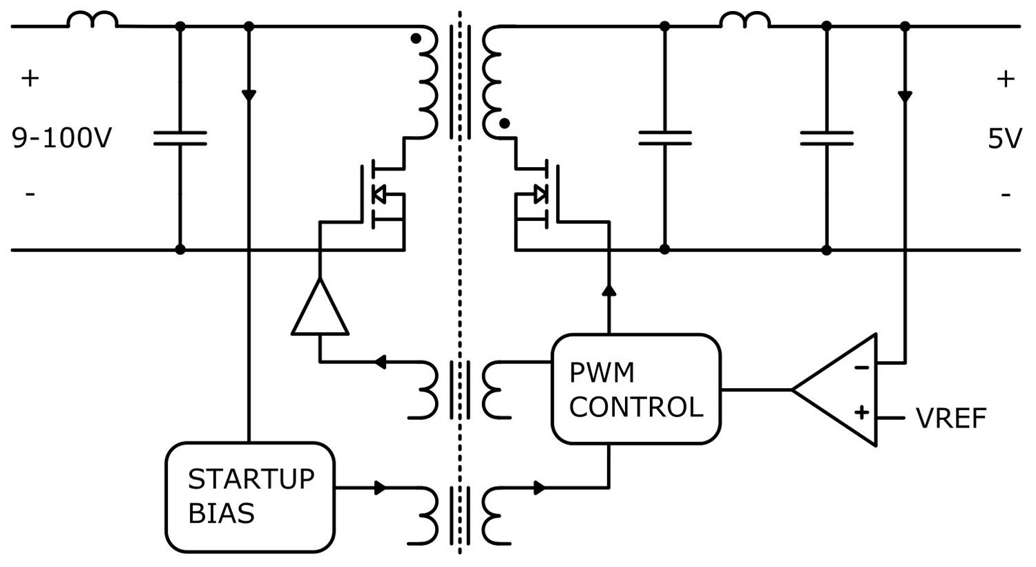
High losses in the output rectifier are remedied by using synchronous rectification. The output rectifier diode is replaced with a low on-resistance, low gate-charge MOSFET. The MOSFET is then switched synchronously out of phase with the primary switch. The voltage drop and hence the power loss on the MOSFET can be lower than that of a Schottky rectifier. The trick is timing the gate of the MOSFET to minimize power loss. Self-drive schemes – where the gate is driven from a transformer – and integrated solutions tend not to work well in flyback converters at high frequency. Driving both the primary and the synchronous MOSFETs from the pulse-width modulation (PWM) controller allows precise timing, which is the key to minimizing power loss. (Figure 1.) The necessary gate drive signal can be transmitted digitally across the isolation boundary.
Figure 1: Flyback topology with secondary side pulse-width modulation (PWM) and control-driven synchronous rectifiers for optimum efficiency.].
(Click graphic to zoom)
|
|
At higher power levels, the flyback topology is still a good option. Instead of beefing up the components, multiple power stages are added in parallel. The stages are then operated out of phase, enabling input and output current ripple cancellation. The cancellation effect is significant, greatly reducing the rms current in the capacitors. It also increases the ripple frequency, further reducing filter size.
Size, weight, and power concerns
Improving power conversion efficiency not only saves energy, but by reducing power dissipated as heat, simplifying thermal design, and even reducing wiring sizes, the technique saves weight. Power conversion efficiency can often be increased by increasing size, but a clever design achieves both smaller size and higher efficiency. Integrating full input voltage transient compliance directly into the DC-DC converter enables a reduction in size and complexity which ultimately improves reliability.
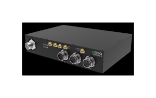
Examples of these wide-range isolated DC-DC converters can be seen in the VXR series from VPT Inc., which have an input voltage range of 9 V to 60 V, can handle transients up to 100 V, and achieve an efficiency rate of as much as 90 percent. (Figure 2.)
Figure 2: The VXR100-2800S from VPT Inc. is aimed at use in applications such as military ground vehicles, commercial and military aircraft, and unmanned aerial and ground systems..
(Click graphic to zoom)
|
|

Steve Butler is director of advanced product development for VPT in Blacksburg, Virginia. He has been with VPT since 1996, and is one of the principal designers of VPT’s hybrid DC-DC converter product line. He has since led the development of VPT’s Hi-Rel COTS and standard space products, as well as numerous custom projects. Steve is currently focusing his efforts on high temperature power conversion. Steve holds Bachelor of Science and Master of Science degrees from Virginia Tech, both in electrical engineering, and has published numerous technical articles and videos. He can be reached at [email protected].
VPT • www.vptpower.com