Introducing VITA 90, the latest rugged small-form-factor module standard
StoryMarch 08, 2022


VITA 90 is a new small-form-factor (SFF) standard that is a direct descendant of VITA 74, an inherently rugged module standard with a compelling space, weight, power, and cost (SWaP-C) proposition, and aimed at use in many military and aerospace applications. Recently, this standard has been causing quite a ruckus within the MIL-rugged embedded systems community, as VITA 90 has been selected by a government-led consortium of manufacturers and integrators for inclusion in the new Sensor Open Systems Architecture (SOSA) Technical Standard.
The VITA 74 rugged module standard was referenced with-in the SOSA Technical Standard Version 1.0 – released in the fall of 2021 – and will be updated to VITA 90 in the upcoming SOSA 2.0 revision, due in late 2022. A typical VITA 74 and VITA 90 module in its simplest form is shown in Figure 1 and is approximately the size of a deck of ordinary playing cards. Both standards have an electronic architecture similar to VITA 65 OpenVPX. For the last two years, there has been a lot of work done behind the scenes to transform VITA 74 into VITA 90 to meet the technical attributes of SOSA.

[Figure 1 | Shown: a typical VITA 74.0/VITA 90.0 19 mm baseline configuration module. Image courtesy Trident Infosol.]
Design considerations for VITA 74.0, VNX
Going back in time, the technology behind this small-form-factor (SFF) standard was initially developed by engineers at Themis Computer. Building on the successful performance of the VITA 57.1 FMC standard, engineers at Themis chose to use the Samtec high-speed, high-density SEARAY connector as its primary module-to-backplane interface, as well as the interface between the backplane and the front panel I/O transition board (IOTB). The right-angle female SEARAY connector was selected to be used on the module, with the corresponding straight male SEARAY connector selected for the backplane. This original NanoATR design defined two module sizes: a 19 mm module using the 400-pin SEARAY, and a 12.5 mm module using the 200-pin SEARAY.
The NanoATR concept was brought to the VITA Standards Organization (VSO) to be considered for a standard describing SFF computer and payload modules to be used in embedded systems targeted towards medium-sized un-manned aerial vehicles (UAVs) and other rugged aerospace applications. The proposal gained both traction and sponsors and became VITA 74, one of three potential SFF standards being considered at the time: VITA 73, VITA 74, and VITA 75. Of the three standards, only VITA 74 had the backing of corporate sponsors for submission to the ANSI standards organization for ratification. After that process was complete, VITA 74 was published as the joint ANSI/VITA 74.0-2017 standard. The standard was given the moniker VNX, a name befitting the unofficial “nano” derivative of VPX.
From its inception, VNX was never intended to replace VPX, but was instead meant to bring the essential tenets of the VPX architecture into rugged airborne, space, and ground platforms that were physically too small to accommodate a VPX system. A typical four-slot avionics display processor system based on the original ANSI/VITA 74.0-2017 standard is shown in Figure 2.

[Figure 2 | Shown is a VITA 74 image processor with optical MT interconnects. Image courtesy Elbit America.]
The ANSI/VITA 74.0-2017 base standard was released with a list of future dot-standards that were to be designed and implemented to optimize complex VNX system I/O solutions for future applications. Two of these dot-standards would add the concept of backplane “Connector Modules” required to facilitate high-speed / high-bandwidth optical and coaxial RF / Video data transmission for both inter-slot and intra-system digital signaling. Another dot-standard would define options to include wedgelocks, address electromechanical considerations for single-module deployments, and define techniques for high-efficiency/high-power VNX module and system cooling. Similarly, another dot-standard defined VNX-specific power supply modules.
VITA 74.4, also known as SpaceVNX, documents specific electronic and mechanical considerations required to implement rad-hard and rad-tolerant VNX solutions in small spacecraft applications. In the process of developing these dot-standards, the VITA 74 Technical Committee reviewed the government and industry’s evolving module performance requirements and use cases; the committee decided to go all in and fully optimize the original VITA 74.0 VNX compute and I/O module’s pin assignments for maximum signal integrity, as well as implementing the OpenVPX-style utility plane, control plane, data plane, expansion plane, and I/O overlays.
Expanding VNX for high-speed fabrics and coaxial/optical signaling
The evolution of VNX from a simple module standard to a family of standards that will describe the technology re-quired to assemble complex SFF systems has been driven by military and aerospace adopters of the ubiquitous VITA 65 OpenVPX family of standards within the VSO, SOSA, and the Hardware Open Systems Technologies (HOST) communities. As a result of evolutionary changes to the SEARAY connector pin assignments, the signal integrity of all high-speed channels has noticeably improved, and the revamped planes can now exceed the signaling requirements necessary to support PCI Express 4.0 and other modern fabrics.
As companions to the SEARAY connector, new VNX connector modules have been specifically designed and manufactured to support various combinations of high-speed signaling: fiber-optic connectivity using MT ferrules, coaxial connectivity for RF and video signals, and isolated copper contacts for applications such as providing high voltages to an RF amplifier’s power supply rails. An example connector module hosting two 24-fiber MT ferrules, 16 #20 silos for Samtec’s 50-ohm RF edge mount (module) or in-line (backplane) coaxial contacts, and four #16 silos for either Samtec’s future in-line (backplane and module) 50-ohm RF, 75-ohm video, or 20-gauge copper contacts, is shown in Figure 3.
These evolutionary changes were deemed to be such a revolutionary improvement over the capabilities of the ANSI/VITA-74.0 VNX base-standard, that both VITA and SOSA management decided that the new capabilities should be codified in a new family of standards – ANSI/VITA 90 – which is called VNX-Plus (VNX+).

[Figure 3 | Shown: A VITA 90 VNX+ module base card with 240-pin connector and full connector module. Samtec photo.]
VNX+ not only includes Samtec’s 400-pin SEARAY connector as defined in the VITA 90.0 base standard, but also includes new additions necessary to support use cases such as signal processors, radio transceivers, graphics processors, network and fabric switches, and other I/O modules requiring coaxial or optical MT signaling. These applications will use the 240-pin SEARAY high-speed data connector with a full-connector module, or the 320-pin SEARAY connector with a half-connector module as defined in the VITA 90.2 dot-standard. VITA 90.3 introduces the VNX+ energy con-version module (power supply) using a 320-pin SEARAY connector centered in a VNX+ slot, and an energy storage module (hold-up capacitor and/or battery) using a 240-pin SEARAY connector, similarly centered in a VNX+ slot. Examples of some of these VNX+ implementations are shown in Figure 4.

[Figure 4 | Shown: An example of a VITA 90 VNX+ backplane. Samtec photo.]
With careful engineering of the mechanical and thermal considerations, VNX+ modules can fit in many tight spaces using conventional backplanes or microbackplanes for single-module deployments. For specific applications, additional space may be recovered by employing an equivalent cabled backplane.
Pod-mounted sensor processor deployments
Considering the tight space inside a 5-inch tube (like an AIM-9 Sidewinder-sized pod), previous systems used ex-pensive custom hardware that was hard to upgrade as threats and requirements changed. Current thinking in the SOSA and other similar communities requires the ability to upgrade or modernize hardware to keep up with the ever-evolving threats, and that requirement drives them to specify and procure standard modules with known hardware and software interfaces. Like SOSA’s modular open systems approach (MOSA) standard OpenVPX, VNX+ is de-signed to meet those requirements.
Military integrators have discovered that the VNX+ size, weight, power, and cost (SWaP-C) attributes make the standard a natural fit for not only SFF traditionally pack-aged ATR-style avionics boxes, but also for pod-mounted sensor and weapon systems requiring high-performance sensor interfaces in close proximity to FPGA [field-programmable gate array] and MPSoC signal processors, computers, radios, and platform I/O available as COTS [commercial off-the-shelf]/mCOTS [military COTS] MOSA modules with standardized electromechanical backplane interfaces. VNX+ is the only backplane-centric COTS MOSA standard which can be deployed as vertically oriented conduction-cooled modules on a traditional horizontal backplane, mounted longitudinally (i.e., along the long axis), within the usable area of a 5-inch diameter tube as used for an AIM-9X Sidewinder-sized sensor pod, or within a 6-inch diameter tube as used for the Coyote, as well as other similarly small payload pods or UAV fuselages. (Figure 5.)

[Figure 5 | Shown is a VNX+ example system in Coyote and AIM-9X pod. Collins Aerospace image.]
Another SFF standard included in the OpenVPX family and SOSA 1.0 is called “Short VPX” (sVPX). sVPX is purposely designed to be the same width as a conduction-cooled 3U VPX module, with the same connector and connector module, except that the PCB area is reduced to 100 mm by 100 mm, instead of the full 3U size of 160 mm by 100 mm, but with a significantly wider slot pitch. Figure 6 shows a 6-inch Coyote-sized housing with a VNX module and an overlaid sVPX module, shown without the VPX backplane and I/O connectors.

[Figure 6 | Examples of VNX+ & sVPX modules in 5-inch and 6-inch diameter pods are shown.]
As the sVPX module is too large to fit in the available space, it can be shown that sVPX, oriented vertically as shown, is best suited for 7.0-inch tube or nonstandard ap-plications. Similarly, the full-size 3U VPX modules are best suited for 10-inch or larger tubes when oriented the same vertical manner. However, 3U VPX modules are often efficiently mounted horizontally in systems of this size, with enough vertical space to enable stacking of the requisite number of modules.
Space use case considerations
VNX is also being designed into space applications. SpaceVNX (VITA 74.4) and SpaceVNX+ (VITA 90.5) were designed from VNX’s inception to target small sats, including 1U to 12U CubeSats, and also for space rovers for critical applications that require high levels of computing and data-transfer performance. SpaceVNX+ follows the high-reliability philosophy of SpaceVPX but considers the size, weight, power, and cost (SWaP-C) constraints related to small sat-based missions.
The SpaceVNX+ in-band protocols such as SpaceFibre, SpaceWire and Serial RapidIO and in-development high-performance compute modules will enable future missions such as multiple spacecraft flying in formation to create unprecedented telescope and interferometers for imaging fainter, smaller, and more distant objects. Swarms of SpaceVNX+ assets will enable complex and time-varying networks of spacecraft and sensors that are capable of sharing rich, near-real-time streams of information to enhance space situational awareness and autonomous operations.
Using an available rad-hard electrical power supply (EPS); a rad-hard system controller/monitor module; and various COTS, modified COTS, or rad-tolerant sensor, processor, or I/O modules, lower-cost rad-tolerant systems are being developed by several organizations. (Figure 7.)
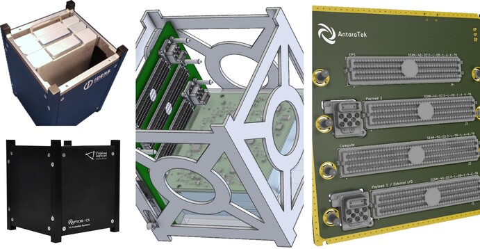
[Figure 7 | Pictured is a 1U CubeSat with SpaceVNX modules. Photos: Trident-Infosol, Ideas-Tek, Antara Teknik.]
VNX+ thermal performance targets
When VITA 74 was first released, the designers of the VNX standard assumed that the practical power limit for the 19 mm module should be arbitrarily pegged at a conservative 20 W. As time went on and integrators started building actual systems in ever-smaller platforms, performance demands inevitably increased, and the use of one or more 20 W to 25 W processor modules became commonplace. These systems employed heat sinks consisting of nominally sized heat-radiating fins coupled with minimal airflow. Testing proved that well-designed VNX systems could be qualified to meet typical military and aerospace environ-mental requirements.
But how small is small enough? Demands to fit in ever-tighter spaces, coupled with faster and wider data paths between sensors, signal processors, and compute modules, has made it necessary for VNX+ to support higher-power components and even denser module packaging. The pow-er rails and grounds are enhanced in the new standard. New options include a legacy balanced 3.3 V, 5 V, and 12 V power system or a new unbalanced “12 V heavy” power system. The VNX+ energy conversion module (ECM) dot-standard is proposed to allow up to three load-sharing power modules to be used in a system, with a companion energy storage module providing input power dropout and transient protection. Some individual ECMs are capable of delivering well over 100 W to the payload modules, but the ECM’s output is purposely derated to ensure that the individual supply’s maximum ratings are never exceeded. The integrated system must employ appropriate cooling technologies for its specified environment.
To understand the thermal limits of individual modules constructed using differing cooling strategies, studies are being conducted to define the upper power dissipation boundaries of practical VNX+ signal processing modules. Figure 8 shows initial thermal modeling employing three different thermal conduction strategies, intentionally exceeding the expected module capabilities, in an effort to bracket the design limits of the three different materials. Three power dissipation levels, 35 W (low power), 55 W (medium power), and 95 W (high power) are modeled, with initial results showing that the all-aluminum module shells with a simple thermal interface will result in unmanageable temperature rises at all specified power limits.
The moderately advanced thermal-mitigation techniques, using copper as the thermal conductor, limit the temperature rise to manageable levels for modules dissipating up to 50 to 60 W. The highly advanced thermal-mitigation techniques show significant improvements in thermal transport, showing a near 20 °C improvement in temperature rise for modules dissipating up to 95 W. Note that the example analysis uses two nearly perfect heat sinks which are assumed to be in very good contact with two of the three available module cooling faces, i.e., utilizing the two module side faces, but not the handle face. In practice, optimal results would be achieved by using all three cooling faces and minimizing the thermal resistance between the VNX module’s cooling faces and the corresponding heat sinks. The type and quality of the selected heat sink will vary depending on the space available and system thermal performance requirements. A practical system could be cooled using a highly efficient heat exchanger or cold plate, in contact with an optimized thermal transfer material, which is in contact with all three VNX module cooling faces. The thermal-transfer material selected can range from a layer of compressible thermal interface material (TIM) to a thin layer of highly efficient thermal grease.
Considering the mechanical envelope studies discussed earlier, coupled with a little algebraic extrapolation, it ap-pears that a system requiring a reasonable number of high-power SFF modules, each dissipating 60 to 80 W or more, which must be constrained in a very small package (such as a 5-inch diameter sensor pod), may now be built using a standards-based architecture employing practical advanced cooling technologies, such as oscillating heat pipes (OHP), to carry the heat away from the module to the dissipating thermal interface. This technology has been proven to be able to transport heat with a small temperature gradient, and if properly positioned, to essentially create an isothermal interface to designated heat transfer locations.
Use of OHP technology should enable multiple modules to each spread their thermal load evenly across their primary thermal interfaces, with a large number of VNX+ modules oriented vertically along the long axis of a small diameter sensor pod, with the internal chassis cooled by conduction, ram air, fan forced air, or a liquid cooled heat exchanger. As the VNX+ thermal envelope is expanded, the advanced cooling technologies will be thoroughly characterized in a real-world VNX+ modular application. These high-power use cases are being verified through continued modeling and laboratory testing. Test results and use case examples showing the expanded limits of the VNX+ power dissipation envelope will be published. (Figure 8.)

[Figure 8 | Modeled data bracketing the thermal performance of VNX modules with material variances.]
Coming soon in the VNX and VNX+ family of standards
Many modules with functionality required for compute, signal processing, communications, and I/O are available or in work. Examples of VNX and VNX+ modules which exist today are currently evolving from existing VNX de-signs, or are new designs in process, include:
• Power conversion and energy storage modules for low-, medium-, and high-power systems
• IA compute modules with up to 11th-generation dual-core Intel Core i7 processors (formerly Tiger Lake), and current generation quad-core Intel Atom processors
• NVIDIA GPGPU modules using the Jetson AGX Xavier GPU processor
• FPGA modules using various SoCs and MPSoCs with Arm cores, using high-speed copper and optical backplane interfaces
• RF transceiver modules using RFSoCs as well as MPSoCs and companion transceiver
• Rad-hard controller modules for space applications
• I/O modules for MIL-STD-1553, ARINC 429, and MIL-1394B/AS5643 data buses
• I/O modules with RS-232/422/485, CAN, and Gigabit Ethernet interfaces
• Gigabit Ethernet switches with L2/L3 and 10 GbE uplink ports
• Storage modules using mSATA SSDs
• MEMS inertial measurement units with GPS
As the military and aerospace communities move to small-er and more intelligent platforms, the requirement to build smaller systems becomes ever more important. To get more “bang for the buck,” there is an enlarging paradigm shift away from custom electronics towards COTS and mCOTS solutions. To minimize the effort required to up-grade systems through the use of common hardware, communications, and control interfaces, it is necessary to build hardware which can be conformant with MOSA standards from ANSI/VITA, SOSA, HOST, and other consortia. VNX+ is being designed and implemented with all of these requirements in mind.
Bill Ripley is the co-chairman of the VITA 90 VNX+ Technical Working Group and is also an engineer and business-development consultant serving for the embedded computing industry, specializing in development and sales of high-performance standards-based, small-form-factor, embedded computers deployed in military and aerospace rugged electronic system applications. Readers may get in touch at [email protected] or [email protected].
Andy Walker is associate director, Mission Systems Advanced Technology Center, at Collins Aerospace. His previous work ranges from devices for advanced radar systems to GaN and SiC devices for electric vehicles. His current pursuits include multifunction RF systems to provide stand-in capabilities in attritable platforms by leveraging the scalability of open standards across disparately resourced platforms. Contact him at [email protected].
Mehmet Adalier is CEO and founder of Antara Teknik LLC. He leads the innovation and development of interoperable, efficient, and secure communications and assured cross-domain solutions on Earth and in space. He is currently driving delay/disruption tolerant solutions for cislunar and deep-space communications utilizing SpaceVNX+. Contact the author at [email protected].
Samtec · https://www.samtec.com/
Collins Aerospace · https://www.collinsaerospace.com/
Antara Teknik · https://www.antarateknik.com/