Operating in degraded visual environments
StoryOctober 16, 2023

Rich Jaenicke
Green Hills Software, Inc.
Operating an aircraft in a degraded visual environment (DVE) is one of the most challenging and stressful tasks for a military pilot, particularly during landing. There are many causes of DVE conditions, including naturally occurring smoke, fog, smog, clouds, sand, dust, heavy rain, blowing snow, darkness, and flat light. Those conditions can happen in combination, and some of the most challenging DVE is induced by the aircraft itself, creating a brownout or whiteout from dust, sand, or snow. Mitigation solutions for the problem of operating aircraft in a DVE fall into a few broad categories: enhanced vision, synthetic vision, and a combination of the two.
A solution to the problems encountered while operating an aircraft in a degraded visual environment (DVE) can be one of several applications in an integrated modular avionics (IMA) system. An IMA platform needs to provide robust partitioning to ensure that any hosted application has no unintended effect on any other hosted application. In a system with a multicore processor, robust partitioning is enabled by meeting the objectives of CAST-32A, including the mitigation of multicore interference.
DVE: Dangers in flight
The primary problem with DVE is the loss of visual references, such as the horizon, the ground, and any nearby obstacles. Situational awareness of terrain and obstacles is required for safe operations during all phases of flight. Loss of situational awareness en route can result in controlled flight into terrain (CFIT) or collision with man-made obstacles. Loss of situational awareness during landing can result in striking obstacles and hard landings. In a helicopter, the loss of visual reference during takeoff or landing can lead to undetected drift or bank of the helicopter or even create a visually induced sensation of self-motion called vection. Those effects significantly increase the risk of dynamic rollover and hard landing, often resulting in aircraft loss or damage and personnel injury or death.
A degraded visual environment has been deemed the most dangerous condition encountered in Army aviation. From 2002 to 2020, 32% of Army Class A mishaps were caused by DVE1. (Class A mishaps involve fatality, total permanent disability, or property damage over $2 million.) While NATO was operating in the arid climates of Africa and the Middle East, rotary-wing brownout (RWB) was responsible for approximately 75% of coalition helicopter mishaps.
It is not just military aircraft that are greatly affected by DVE; DVE-induced spatial disorientation accidents are a leading cause of fatal accidents in civil helicopter aviation. Based on data from the FAA accident database, the civilian helicopter community experienced 130 fatal spatial-disorientation DVE accidents from 2000 to 20192.
DVE flight scenarios
Without significant DVE mitigation, flying in a degraded visual environment can often require multiple attempts to land before being able to observe sufficient landmarks and terrain details or aborting the mission after multiple failed attempts. The consequences of an aborted mission can be huge, particularly for search-and-rescue (SAR) missions. In a military setting, requiring multiple attempts in a hostile environment puts the rescuers in harm’s way for an extended time.
Some examples of critical missions requiring flight in DVE include:
- A combat SAR mission to rescue a pilot shot down deep in hostile territory
- A casualty evacuation mission for a soldier or a firefighter through thick smoke and rotor-induced dust
- A SAR mission to find and rescue the pilot and passengers of small aircraft from a snow-covered mountainous terrain with whiteout conditions
DVE mitigation solutions fall into a few broad categories: enhanced vision, synthetic vision, and a combination of the two. How the imagery is displayed also plays a role, whether on a heads-up display, helmet-mounted display, or heads-down display.
Enhanced vision with sensors
Mitigating DVE starts with sensors capable of penetrating the blinding environmental conditions. A system that provides real-time imagery of the external scene based on such sensors is called an “enhanced vision” system by the Federal Aviation Administration (FAA).
Different types of sensors have different resolutions, obscurant penetration, and update frame rates. For example, infrared (IR) has a high frame rate but has limited obscurant penetration, while millimeter-wave radar penetrates very well but is low-resolution. Lidar has high resolution to detect obstacles and find a flat area to land but doesn’t penetrate obscurants very well, takes several scans to form a complete image, and has a shorter range than other technologies.
Because no one sensor can handle all types of DVE, the most useful DVE solutions use a combination of sensors. The data from those disparate sensors needs to be fused to provide a real-time image of the external scene topography and obstacles. Sensor fusion in an enhanced vision system is computationally intensive and includes georegistering 3D data and scaling, translating, dewarping, and aligning the images. The resulting scene needs to be displayed with low latency, typically less than 100 ms from the time the images were acquired.
When these systems are relied upon for critical stages of flight, such as takeoff and landing, the systems must meet safety-critical requirements, with the software foundation for such a system a safety-critical RTOS.
Synthetic vision
An alternative to enhanced vision is synthetic vision. Synthetic vision is a computer-generated image of the external scene topography relative to the aircraft that is derived from a database of terrain and obstacles coupled with aircraft attitude and a high-precision navigation solution, usually from a GPS. The computer-generated image is typically displayed as background on a primary flight display (PFD), with the PFD guidance symbology displayed on top.
These databases can require a significant amount of memory, depending on the geographical coverage loaded. Additionally, military synthetic vision systems often combine a civilian terrain database with a more specialized military database. To accommodate such large databases, the operating system should support 64-bit memory addresses in order to access more than 4 GB.
Compared to enhanced vision, synthetic vision does not provide a real-time view of the actual external scene, and it is only as accurate as the database and the GPS location. The database can have errors, and the GPS is subject to interference and jamming. On the plus side, synthetic vision has no limitation in range or field of view, which is a compelling reason to augment enhanced vision with synthetic vision.
An example of a synthetic vision system is the SureSight SVS from CMC Electronics, a software application that can run on CMC’s multicore avionics solutions, including the MFD 3068 multicore smart display and the PU 3000 multicore avionics computer. Both of those avionics computers use a quad-core Power Architecture processor. The SureSight SVS runs on top of the INTEGRITY 178 tuMP RTOS and has been certified to FAA’s AC 20-167 and DO-315B. (Figure 1.)

[Figure 1 ǀ Primary flight display (PFD) running the SureSight SVS (a synthetic vision solution from CMC Electronics).]
Enhanced flight vision system
When flying in DVE, pilots have to use aircraft instruments and additional references to perceive motion relative to the Earth. Properly executing basic flight tasks in such a situation is even more difficult while already in a task-saturated mission profile.
An enhanced flight vision system (EFVS) combines flight information, symbology, and navigation guidance of a PFD with the real-time images of the external scene from DVE sensors and presents them to the pilot on a heads-up display (HUD) or equivalent display, such as a helmet-mounted display (HMD) or head-worn display (HWD). This enables an EFVS-equipped aircraft to be eligible for FAA operational credit, which permits certified aircraft to descend below the published instrument approach minimums. Aircraft equipped with an EFVS Approach System can descend to 100 feet using enhanced vision, while those with an EFVS landing system can complete the descent, landing, and rollout using enhanced vision.
One issue with the effectiveness of existing EFVS systems that rely solely on IR sensors is that airports are switching from incandescent lighting to LED lighting for the runway and approach lights. Current EFVS systems depend on the heat generated by the incandescent lights to optimize their performance. Newer EFVS systems combine IR with visible light cameras, millimeter-wave radar, or another sensor to resolve that issue.
FAA Advisory Circular 20-167A requires an EFVS to have a design assurance level of DAL C (Hazardous) or higher, as defined by RTCA/DO-178C, depending on the specific cockpit integrations, failure conditions, and mitigations of those conditions. An EFVS may need to be designed to DAL B (Major) or higher if it is intended to facilitate landing and rollout in DVE.
Combined vision system
A combined vision system (CVS) combines enhanced vision and synthetic vision in a single display, thereby taking advantage of the strengths of both. For example, enhanced vision shows the live view of objects on a runway, such as vehicles, wildlife, and other aircraft; while synthetic vision provides better spatial orientation and movement perception, along with enhanced terrain awareness.
In a basic CVS, the top half of the display shows the synthetic vision and the bottom half the enhanced vision. More advanced CVS combines synthetic and enhanced imagery as overlays for a blended image covering the entire display.
Deployed combined vision system example
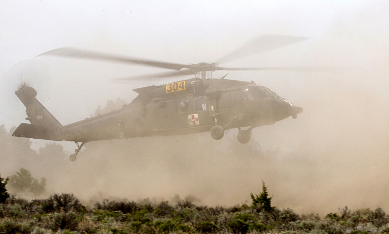
A prime example of a deployed combined vision system is the Degraded Visual Environment Pilotage System (DVEPS) developed by Sierra Nevada Corporation (SNC) under a contract awarded by the U.S. Special Operations Command. DVEPS was first installed on 15 Army HH-60M Black Hawk helicopters – the HH-60M is the medical evacuation (MEDEVAC) version of the UH-60M Black Hawk utility helicopter – in 2021. DVEPS is also installed on MH-60M and MH-47G, which are Special Operations versions of the Black Hawk and Chinook helicopters.
The primary goal of the DVEPS program was to enable landing and takeoff in DVE conditions induced by rotorcraft, namely brownout and whiteout. That is because three-quarters of the helicopter accidents in Iraq and Afghanistan have been attributed to brownout conditions, according to the U.S. Naval Aviation Center for Rotorcraft Advancement. Focusing on rotorcraft-induced DVE enabled DVEPS to create a solution with just two sensors, an IR camera, and lidar, instead of also requiring millimeter-wave radar. DVEPS also uses synthetic vision based on digital terrain elevation data (DTED) and other more specialized military terrain databases, which are augmented by real-time 3D images from the lidar. (Figure 2.)

[Figure 2 ǀ DVEPS sensors mounted on the nose of a Special Operations MH-60M left and right of the camera turret. Photo: U.S. Army United States Special Operations Command (SOCOM).]
SNC’s design of DVEPS is unique in the amount of real-time 3D and 2D sensor fusion performed and the multiresolution 3D database that enables the fusion. The DVEPS sensor fusion process has several steps to create the combined vision display for the pilot:
- The initial 3D terrain database is loaded with DTED and is often augmented with specialized higher-resolution military data for the area around the target landing zone.
- As the helicopter approaches the target landing area before there is any significant brownout or whiteout, DVEPS uses the onboard lidar to capture high-resolution terrain data of the area. Because the lidar data is real-time, it also captures any vehicles, other obstacles, or changes to the terrain. The lidar data is also more reliable than the preloaded database as it does not include any errors in the database or GPS positioning.
- The lidar data is geo-registered and fused with the preloaded terrain databases.
- The resulting 3D multiresolution world model is rendered into a 2D image of the terrain and updated as the helicopter descends.
- The real-time imagery of the IR camera is fused with the terrain rendering to form a combined real-time image of the landing zone. The IR imagery typically has enough image contrast to differentiate between gravel, grass, dirt, and pavement, which would not be differentiated in the lidar data if they all have the same height.
- Symbology is overlaid on the image to provide the appropriate cues for the pilot.
The resulting real-time view of the landing zone is presented on a cockpit display. As the helicopter descent creates the brownout condition, DVEPS continues to use the 3D lidar data gathered earlier while refreshing with real-time IR imagery.
The software foundation for DVEPS is the INTEGRITY-178 tuMP RTOS running on a quad-core Intel Core i7 processor.
DVE solutions require safety-critical operation running concurrently on multiple cores to achieve the necessary real-time performance. Robust partitioning is a prerequisite for a full implementation of integrated modular avionics (IMA) or being able to reuse an application component without complete retesting and reverification of the entire system.
Notes
1 Flightfax, Issue 108, May 2022
2 Recommended Practice: Spatial Disorientation induced by DVE (H-SE 127A), United States Helicopter Safety Team, 9 December 2020
Richard Jaenicke is the director of marketing for safety- and security-critical products at Green Hills Software and has over 25 years of experience working with embedded software and systems. Prior to joining Green Hills, he was at Mercury Systems, where he was responsible for marketing avionics software and hardware solutions as well as signal-processing systems. Rich holds an MS in computer systems engineering from Rensselaer Polytechnic Institute and a BA in computer science from Dartmouth College. Readers may email him at [email protected].
Green Hills Software • https://www.ghs.com/