Remote Monitoring Debriefing System (RMDS) conceived and developed by the Israel Aircraft Industry (IAI)
StoryJuly 08, 2008

Yehuda Singer, Ph.D.
Beyond2000 Ltd.

The Remote Monitoring Debriefing System (RMDS) is intended for the first solo flights of a pilot trainee. It enables the trainer to monitor the flight in real time and to play back the flight later to provide detailed feedback and instructions.
A pilot trainee performing his or her first solo flights could commit errors that could lead to serious accidents. A simple solution is to put a video camera in the cockpit and transmit real-time video to the trainer monitoring the flight from the ground. However, the transmission of a digital video at the rate of 15 frames per second necessitates bandwidth of 160 Mbps. The cost of such a channel is prohibitively expensive. The question is how to avoid transmitting video and still monitor the state of the aircraft in flight. The solution is to perform image processing on the input video and transmit numerical results to the ground. Transmitting numerical results requires a bandwidth of only 9,600 bits per second, which is easily and economically transmitted over an RF radio modem (see Figure 1).
Figure 1
(Click graphic to zoom by 2.0x)
|
|

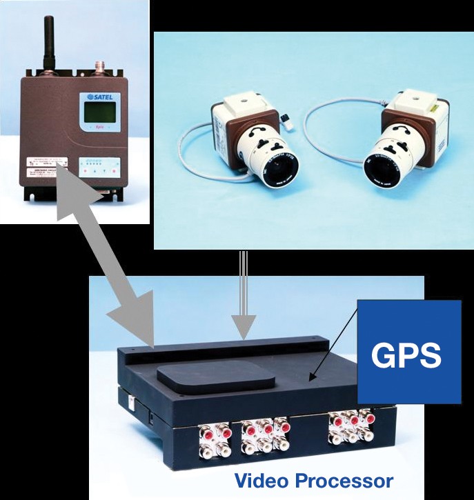
Figure 2 shows the system operation during flight. The aircraft is equipped with cameras connected to the cockpit video processor, a radio modem, and a GPS. The cockpit video processor performs image processing to analyze the state of the meters. The numerical results of the image processing and the GPS data are sent via the radio modem to the Ground Station (GS), which restores the view of the panel and the 3D map as closely as possible to the real view seen in the aircraft. The platform of the GS is based on the FSX-Microsoft Flight Simulator.
Figure 2
(Click graphic to zoom by 1.7x)
|
|
To achieve a ground that is as close as possible to real video, we need to perform image processing at the rate of 15 frames per second on each camera.
System analysis
At the system analysis stage of the project, the computer requirements are:
- CPU load is 30 percent
- The bandwidth of the memory and bus is 40 percent
The assumptions for estimating the usage of these resources are:
- The image processing is performed on a set of Regions Of Interest (ROIs)
- Each ROI is 100 x 100 pixels = 104 pixels
- There are 20 ROIs
- 15 frames per second
- Memory access of 10 ns, which relates to failure in accessing the cache memory.
- A CPU faster than the memory is delayed by the memory whenever it accesses it.
Therefore, to estimate the CPU load, we have to count the number of memory accesses in our algorithm. Since the algorithm does not access the memory sequentially, we take a larger value of the memory access time. Table 1 shows the CPU load, which is much higher than desired: more than 54 percent compared with the value of 30 percent corresponding to the typical requirements. Table 2 shows the required memory bandwidth. It is a little more than 40 percent.
Table 1
(Click graphic to zoom by 2.0x)
|
|

Table 2
(Click graphic to zoom by 2.0x)
|
|

In the next section we shall introduce other considerations in choosing the computation platform for our project.
Choosing a platform
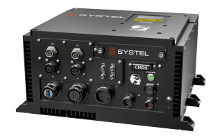
Software development associated within such a project is the critical path; hence, the requirement was to find an off-the-shelf evaluation board with two processors and start the software development without any wait for hardware development. At the end of 2004, we chose the Analog Devices BF561 dual-core as a platform for our project. By choosing the BF561 (see Figure 3), we removed the bottleneck of CPU time.
Figure 3
(Click graphic to zoom by 2.2x)
|
|
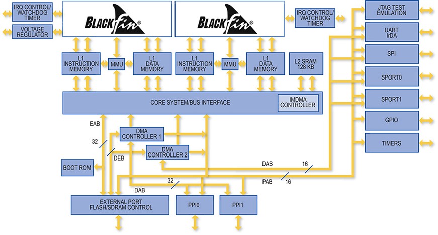
Memory bandwidth is supported by:
- A separate cache for instruction
- A separate cache for data
- A fast DMA to capture streaming video in and out.1 (In addition, the BF561 has standard I/O resources such as RS-232, SPI, and parallel I/O)
Analog Devices' evaluation board, the ADSP-BF561 EZ-KIT Lite,2 enabled us to start software development immediately. I/O not included on the evaluation board was implemented on an extension board connected to the evaluation board via backward connectors.
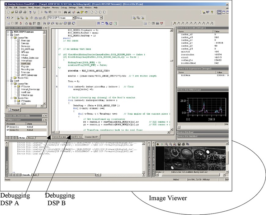
The software tools associated with the BF561 permit one PC to serve as a development platform controlling the two DSPs (see Figure 4). Of course the software development process of a multiprocessor becomes simpler when the development system is controlled by one PC. In addition, software development of a real-time image processing application implies supporting utilities to the Integrated Development Environment (IDE). It is necessary to display the input image as sampled by the video decoder in the DSP. Figure 5 shows an image captured by the video decoder and stored in the DSP's memory. The image is displayed by the image viewer, which is a part of the IDE. This feature helped in integrating progressive scan video cameras. The progressive video is essential in image processing applications in a vibrating environment. The camera produces a TV standard that is 525 lines and 858 columns. The image produced by the camera is at the size of 640 x 492 pixels per frame. The image viewer helped in finding the input video's real size, which is 525 x 858.
Figure 4
(Click graphic to zoom by 2.2x)
|
|
Software design to enhance performance
The two cores interact via a shared memory. The shared memory is an external DRAM controlled by external port flash/SDRAM (see again Figure 3). The utilization of the two cores depends on the functional decomposition of the project. In an ideal situation when the computation task can be decomposed into independent subtasks, the processors are fully utilized. On the other hand, if the functional decomposition yields interdependent subtasks, much time is spent on synchronizing the processors in accessing the data in the shared memory. The design goal is to minimize these interdependencies; hence, the processors become loosely coupled.
Figure 5 shows the functional decomposition of our system. Each DSP has its own cache memory instruction and cache memory data. One DSP samples the video from the camera and performs image processing only, while the second DSP interfaces the external world:
Figure 5
(Click graphic to zoom by 2.0x)
|
|

- To the GS via the RF modem
- To the GPS
- To the contrast control of the cameras
The DSP performing the image processing handles the second DSP with numerical results and the contrast values via the shared memory. The second DSP does not acknowledge the acceptance of these data, reducing our synchronization costs.
This functional allocation of tasks to the two DSPs guarantees that they are loosely coupled; thus, their computational power is maximized.
Video processing
The streaming analog video is captured by the video decoder, which converts it to digital and transfers the converted video to the external memory by one of the DMA channels. When a frame is completed:
- An interrupt is generated to the DSP when a new frame has been received and is stored in memory.
- DMA switches automatically to get an additional frame in a new memory buffer without the interference of the DSP.
The DSP processes the frames concurrently while new frames are captured by the video decoder. To enhance performance, portions of the images that relate to the ROIs are transferred from the DSP's external memory to its internal memory.
To enable debugging in real time, we produce an image with video markers on a monitor TV that shows the last frame processed. However, our input video is a progressive scan type, while a monitor TV supports interlaced video.
Figure 6 lists line information on the two types of video. A progressive scan video frame is composed of a contiguous sequence of 525 lines starting at line 0 and ending at line 524. An interlaced video is composed of two subframes: One subframe is a sequence of all even lines starting at line 0 and ending at line 524; the other subframe is a sequence of all odd lines starting at line 1 and ending at line 523. We again used the fast DMA that is part of the BF561 to convert the progressive video to an interlaced video. In addition, we added special markers to show the results in video for debugging and recording for debug purposes.
Audio handling
To enable communication between trainee and trainer outside the normal avionics communication channel, we added voice handling via the radio modem. The radio modem works at the baud rate of 9,600 bits per second. The bandwidth for the voice is 3,200 bits per second from the global baud rate of 9,600. The solution is to perform compression and decompression in the DSP that interfaces with the external world. The trainer has a microphone and an earphone connected to the GS. The GS compresses the trainer's voice and sends it via the RF modem to the BF561; the BF561 decompresses and activates the audio decoder, which is connected to the trainee's earphones. The trainee can speak to the trainer through his or her microphone, and the BF561 compresses his or her voice and sends it via the RF modem to the GS. In the GS, voice restoration is performed and routed to the trainer's earphones. The convention in avionics systems is half-duplex communication. Voice handling involves interacting with the audio code, Serial Port (SPORT), and the DMA. The digital interface of the audio codec is the SPORT. Audio streaming is supported by the DMA.
Project status
Our version of the project is now working. The BF561-based system performs image processing at the rate of 14.7 frames per second; the numerical results are transferred via the RF modem to the GS, which restores the panel and the 3D and 2D maps. The computing load of the BF561 is around 80 percent. Now we are working to optimize the code and enhance internal memory usage by transferring only the regions of interest of the frame to the internal memory. Our goal is to reduce CPU load to 40-50 percent.
Dr. Yehuda Singer received his Master's of Science from Weitzman Institute and his PhD from Bar-Ilan University. He has more than 28 years of experience in embedded systems, computer architectures, and FPGAs. Since 1995, he has acted as the CTO of Beyond2000 Ltd., which is an outsourcing company. He can be reached at [email protected].
Beyond2000 Ltd.
972-8-9265333
www.be2k.co.il