Bridging the cooling gap in high-speed embedded systems
StoryAugust 13, 2020

By Steve Gudknecht and Jordan Sudlow
In the high-performance world of VPX for defense applications, aggregate payload power calls for creative strategies when addressing cooling at the chassis level as well. New high-performance applications will demand new inventiveness, if not outright new inventions, in applying and adapting established chassis-level cooling techniques while keeping costs down. Properly engineered VITA 48.2 chassis using air or liquid assist are capable of cooling payloads far more effectively compared to conduction-cooled-only chassis. These design extensions for 3U and 6U systems enable cost savings in applications which can support air and liquid cooling by leveraging a well-established VITA 48.2 supplier ecosystem.
Years ago, a certain product manager said to a group of engineers, “Don’t show me a product development schedule with an invention in the middle of it!” That advice comes to mind when developing new VPX systems that enable unprecedented computational power in mission-critical defense applications. With the advent of individual 6U VPX modules that surpass 200 W of dissipated power, traditional conduction cooling approaches for heat removal are being pushed to the limit and with that we see the emergence of the various VITA 48 module level cooling strategies.
Board-level cooling vs. chassis-level cooling
Managing heat dissipation in VPX systems tends to divide into two areas of concentration where solutions point to board (VPX module)-level cooling on one hand or to chassis-level cooling on the other. In the former case, much effort has gone into developing the VITA 48 REDI [Ruggedized Enhanced Design Implementations] standard and its underlying module-cooling specifications. While those specifications require chassis-level supporting infrastructure, their mechanical design addresses heat transfer at the module level. Each one uses cooling methodologies branching from VITA 48.2 (conduction-cooled). Much of the design effort to date has centered around 6U modules versus 3U, since the functional density in larger 6U modules pushes heat-dissipation requirements beyond the point where 48.2 is effective.
Stretching the limits of VITA 48.2 chassis design
Most VPX systems use VITA 48.2 conduction-cooled modules due to an established deployment track record. As module power continues to increase, however, VITA 48.2 struggles to dissipate the attendant heat using straight conduction cooling. System designers therefore have two choices: Either move to VITA REDI alternatives or stick with VITA 48.2 and stretch the limits at the chassis level.
The choice is a difficult balancing act between conflicting demands like cost, module availability, chassis design, environment, size, and weight. One thing is almost certain: Whether at the chassis or module level, air or liquid cooling will play a role. Power-hungry modules can leverage one of the thermally advanced VPX REDI standards, such as VITA 48.4 (liquid) or .8 (air), but when these modules are not readily available, the system designer will need to use hybrid cooling strategies using VITA 48.2 modules.
Given their performance record, broad supplier ecosystem, and availability in a wide range of functions, the goal is to get the most out of VITA 48.2 modules. They use known chassis infrastructure and are far less expensive compared to VITA 48.4/.8 versions that require precision machined conduction-cooling frames supporting inlet and exhaust passages (AFT, .8) and inlet/outlet quick disconnect mechanics (LFT, .4) for heat removal. VITA 48.4 /.8 modules are not widely available in 6U and less so in 3U (which are not addressed by 48.4). The dearth in 3U modules makes system-level cooling alternatives for that form factor even more important.
Hybrid chassis design
In 3U and 6U, extending the cooling capacity of VITA 48.2 chassis involves adding air or liquid assist to create hybrid designs that amplify the effect of the baseline conduction hardware. Thermal modeling and empirical data indicate that the cooling capacity in conduction-only chassis can be increased substantially when applying air- or liquid-assist options. (Table 1.)
 [Table 1| These numbers compare cooling capacity using passive, air-assist, and liquid-assist conduction cooling in six-slot VITA 48.2 3U VPX chassis.]
Air-over-conduction design
In a VITA 48.2 chassis, heat is conducted away from hot module components through the heat sink and out to the module wedge locks. Using air assist, an air-over-conduction cooled (AoC) VITA 48.2 chassis channels air through the chassis side walls in a direction perpendicular to the wedge locks. The chassis side walls contain cooling heat sinks and fans to supply adequate pressure and flow rate. The walled areas form enclosed air chambers isolated from the modules, which envelop the payload section and concentrate air flow. Forced air runs coplanar to heat sink fins, drawing away excess heat. (Figure 1.)
[Figure 1 | Example airflow pattern in a conduction-cooled chassis with air assist.]
Liquid-over-conduction design
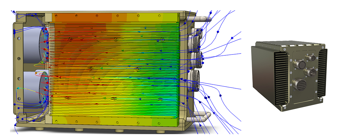
Liquid-over-conduction (LoC) VITA 48.2 chassis are used for high-performance thermal requirements where air assist is insufficient, and where the application can support an external pump and chiller. LoC chassis channel the coolant perpendicular to the card edges through system cold plates (chassis side walls) in a fashion similar to AoC chassis. Two popular coolant choices are EGW [ethylene glycol water] and PGW [propylene glycol/water] mixtures where the glycol additive serves as an antifreeze. Additionally, PAO [polyalphaolefin] sees popularity among military and aerospace applications primarily due to its dielectric properties. (Figure 2.)

[Figure 2 | Example of liquid flow pattern in a conduction-cooled chassis with liquid assist.]
Cold plate design
A potential game changer in cold plate design is the rise of 3D printing, also known as additive manufacturing. Cold plates today are typically fabricated by machining the fluid channels into complimentary halves of a plate. The halves are then joined using dip brazing or vacuum brazing. It’s a lengthy and expensive process; moreover, if cold plates are not properly flushed, salts used in the brazing process may contaminate working fluid or be ingested into pumps. In contrast, new 3D manufacturing enables precise location and layout of fluid channels while reducing lead time and costs.
For less rugged applications, a new design approach in producing liquid-cooled cold plates involves the use of a primary plate that incorporates integrated gasketing for O-rings, the flow channel, and cooling fins. A bolt-on plate compresses the O-ring gaskets in place. Separate O-rings enclose the channel and encircle retaining hardware in the center. Synthetic rubber O-rings provide service temperatures from -65 °C to 150 °C.
Heat sink design
Optimal heat sink design for both AoC (air) and LoC (liquid) chassis requires the use of high-power press-style fins that enable higher fin density compared to milling techniques and provide more heat-dissipating surface area than can otherwise be achieved. For AoC applications, cooling fans should be chosen based on flow rate, acoustics, reliability, and static pressure. Forced air passes coplanar to the fin surfaces along the length of the chassis, so fin density must be balanced between optimal dissipative capacity minimal air flow resistance. Temperature sensors regulate fan speed to maintain target temperatures. For LoC applications, typically the chassis is one of many items on the system-cooling circuit which may include a chiller and pump. Chassis design therefore centers on optimizing heat sinks for the predetermined flow rate.
Environmental use cases
Air- and liquid-assist designs should maintain card-edge temperatures of 70 °C and 85 °C for standard and extended temperature versions, respectively. The selection is based on the system operating temperature, which can range from -40 °C to 71°C. When determining whether to employ AoC or LoC cooling, both models should be assessed.
AoC cooling is relatively simple and requires little external infrastructure to support chassis operation. Applications for these systems include air, land, and sea assets where space constraints, cabin environments, and altitude can tolerate larger system footprints and air pressure is sufficient for fan cooling. AoC cooling will, however, see reduced performance during high temperatures and altitudes.
LoC cooling applications for embedded systems are becoming increasingly prominent. Advantages of this method include increased thermal dissipation and higher tolerance with regard to ambient temperature and altitude. For LoC systems, inlet fluid temperature and fluid flow rate largely determine payload temperature. A drawback of liquid cooling is that the system requires external resources including chillers and pumps to provide the coolant; due to these factors, they lend themselves to larger air, land, and sea assets with fewer space constraints.
Liquid closed-loop cooling
Chassis suppliers are investigating leading-edge solutions to address the external resource requirements of liquid cooling. Closed-loop chassis, for example, integrate the pump, radiator, and coolant reservoir into the control volume of the chassis, eliminating the need for external cooling hookups. The working fluid forms a “closed loop,” which recirculates continuously around the chassis transporting heat away from the hot payload. Early results are promising.
Steve Gudknecht is the product marketing and communications manager at LCR Embedded Systems. He has more than 15 years of experience promoting and managing solutions for the embedded computing industry. Steve also served as marketing manager for ACT Technico and later for Elma Electronic. Jordan Sudlow is a mechanical design engineer at LCR Embedded Systems. Jordan is a graduate of Geneva College and has been with LCR for two years, specializing in VPX chassis design, FEA simulation, and thermal-fluid applications.