A new approach to testing embedded-LO converters
StoryAugust 12, 2009

David Ballo
Agilent Technologies
Though they offer significant advantages compared to spectrum-analyzer-based methods, traditionally, vector network analyzers have not been used to characterize the group delay of analog satellite transponders, due to the lack of access to the RF signals or the time bases of the internal Local Oscillators (LOs) within the transponder. A new way to make group delay measurements of embedded-LO converters with modern VNAs will yield increased measurement speeds and significant accuracy improvements.
Vector Network Analyzers (VNAs) provide fast and accurate S-parameter measurements of a variety of RF and microwave devices. S-parameters are the core of many common measurements such as gain, match, and group delay. While S-parameters have been traditionally used for non-frequency-translating devices such as filters, amplifiers, and antennas, in recent years, methods have been invented that extend S-parameter measurements to frequency-translating devices like mixers and converters. It is relatively easy to measure mixers and converters when external Local Oscillators (LOs) can be supplied to the Device-Under-Test (DUT), or when the DUT’s internal LOs and the VNA can be locked to a common time base. However, for DUTs with embedded LOs, when there is no access to the RF signals or the time bases of the internal LOs, measuring group delay is particularly challenging.
Satellite transponder challenges
The most common type of converters with fully embedded LOs are satellite transponders. Single-conversion analog satellite transponders have been around for many years. The transponder takes a signal sent from an Earth station to the satellite and sends it back down to Earth at a different frequency. This single-conversion architecture has a variety of advantages and is still widely used today.
To characterize these transponders, a variety of key measurements is needed. First, it is necessary to make sure the transponder has sufficient gain to boost the signal for the long trip back down to Earth. Next, gain flatness is verified to make sure that signal shape is maintained across the frequency band. Phase and group-delay linearity through the satellite are also very important, to minimize inter-symbol interference in digitally modulated signals. Port matches must be measured to ensure minimal mismatch ripple when the transponder is connected to cables and antennas. Finally, noise figure is also important as operational signal-path losses are large, so receiver-contributed noise must be minimized.
Complicating matters, these key measurements must be tested over a variety of conditions. First of all, modern satellite transponders must be tested over many frequency bands. And since satellites operate in very harsh environmental conditions in space, a wide range of test data at different temperatures must be accumulated on the ground to validate flight worthiness. Finally, to ensure the utmost reliability, transponders are typically tested at several stages in their development, beginning at the circuit level, then the module level, and finally, the systems level.
With many parameters to characterize under many conditions, testing transponders becomes a time-consuming endeavor, producing large amounts of data. Adding to the challenges, often many of these tests are conducted on costly outdoor ranges, in indoor hi-bay test areas, or even worse, in Thermal-Vacuum (TVAC) facilities that are very expensive to operate and can be slow to reach the desired environmental conditions. When these tests are executed as the satellite nears completion, there are high expenses in manpower and materials that make it desirable to finish the job quickly so the satellite can be shipped to the launch pad, thus expediting payment to the manufacturer. This pressure directly translates to a strong desire for faster measurement speeds to quickly capture the tremendous amounts of data necessary to ensure solid performance of the satellite.
Traditional test systems
In concept, the traditional approach to testing analog satellite transponders is simple. Traditional stimulus-response testing stimulates the satellite transponder with a signal generator at the appropriate frequencies, and measures the output of the transponder with a spectrum analyzer.
Using a signal source, a spectrum analyzer, and directional couplers (Figure 1), scalar measurements can be made of conversion gain and input match. For group delay measurements, the envelope-delay method is typically used, where a carrier with AM or FM is stepped across the transponder band. The advantage of this approach is it does not require phase coherency between the test system and the DUT, so there is no need for access to the transponder’s internal local oscillators. However, there are significant disadvantages to the traditional stimulus/response approach. Compared to using a VNA, test times are considerably longer. Also, accuracy suffers as vector error correction, which is commonly used with VNAs, is not available with a source/spectrum analyzer combination. The envelope-delay method for measuring group delay tends to give noisy results, requiring averaging to improve signal-to-noise ratios, at the expense of measurement speed.
Figure 1: Traditional scalar approach to transponder test using a signal generator and spectrum analyzer plus external couplers and switches.
(Click graphic to zoom by 1.7x)
|
|

Finally, there’s no vector reflection information provided in the traditional scalar system. Modern transponder testing often requires measurements of S11 and S22, which is easily accomplished by a VNA. Without these S-parameters, modern de-embedding techniques used to remove the effects of cables and test adapters cannot be used. This can be a big problem when the calibration cannot be performed at the DUT’s test ports, which often occurs in TVAC facilities.
Using VNA-based systems for characterizing converters
All of the measurements previously described can be done using a VNA. Measuring conversion gain and vector input and output match of embedded-LO converters is easy with modern VNAs. With these instruments, the stimulus source and the measurement receivers can be tuned independently from each other, using the analyzer’s frequency-offset mode of operation. This approach is much faster than the traditional stimulus/response system based on a source and spectrum analyzer. The speed improvement is due to the fast synchronization of the source and receivers as they are swept in frequency, compared to using instruments controlled by a computer via GPIB or LAN. In addition, VNAs have test couplers built in and they can perform forward and reverse measurements, providing S11 and S22 of the DUT, with the high accuracy provided by vector error correction.
For scalar transmission (gain) measurements, there is no need for access to the DUT’s LO. The IF bandwidth of the analyzer must be wide enough so that the frequency offset from the nominal value of the DUT’s LO gives insignificant error. With one extra sweep, the offset value can be directly measured if desired, so that the receivers can be tuned more accurately to the output frequency of the DUT, and narrower IF bandwidths can be used for lower noise.
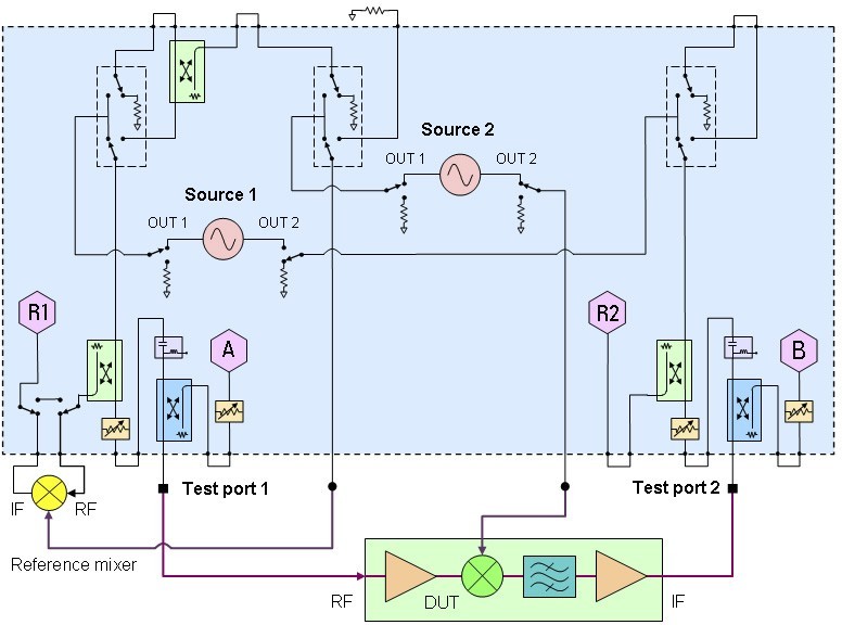
To measure the transmission phase (and group delay) of a converter, a reference mixer must be added to the setup. The reference mixer provides a signal to the reference receiver of the VNA that is at the same frequency as the output frequency of the DUT. In this way, the phase difference between the reference and test signals can be measured, providing phase versus frequency information. Group delay can be easily calculated from this underlying phase information by performing a finite-frequency differentiation.
Figure 2 shows how the reference mixer is used with an instrument like Agilent’s PNA-X Series of network analyzers for measurements of converters that don’t have embedded LOs. The reference mixer is placed in the reference receiver path using the front-panel access points that are available on most modern VNAs. The network analyzer can simplify the test setup by using the optional built-in second signal source to provide the LO signals. This arrangement is very fast, since the two sources and the receivers are synchronized with the VNA’s internal hardware and software.
Figure 2: When using a VNA for phase and group delay measurements of converters, a reference mixer is needed to provide a reference signal that is the same frequency as the output of the DUT.
(Click graphic to zoom by 1.7x)
|
|
Let’s take a look at extending our converter measurement technique for devices with internal LOs. There are three different scenarios, each with a different level of noise (and therefore, accuracy) resulting from the phase noise of the LOs (Figure 3). The best scenario is the “phase-synchronous” or common-LO case. With this setup, there is direct access to the internal LO, so that a portion of it can be used to drive the reference mixer. The next best scenario is where the LO itself is not available, but there is access to its time base, which can then be locked to the time base of the reference mixer’s LO. The toughest scenario is the fully embedded case, which represents most transponder-test situations.
Figure 3: Group delay noise depends on the LO arrangement. With a common LO, noise is minimal. Two LOs with a common time base provide an intermediate level of noise. The fully embedded case is the most difficult to measure.
(Click graphic to zoom by 1.7x)
|
|

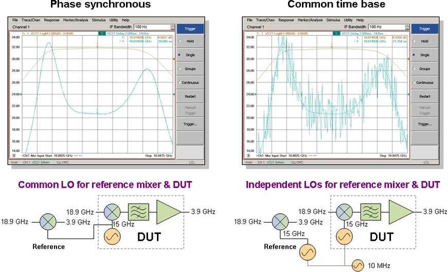
The common-LO case gives the least amount of delay noise because the phase noise on the LO is present in both the reference (R1) and test (B) receivers. Since phase measurements are relative between the two receivers, the LO’s phase noise is ratioed out of the measurement. For DUTs with inaccessible LOs but with time-base access, the reference mixer and DUT are driven by different LOs that are locked to a common time base (10 MHz, for example). This means their average frequency is the same, but the phase variations due to their inherent phase noise will be different. The two LOs are coherent in frequency, but not phase synchronous. Since the signals in the reference and test receivers are derived from different LOs, their phase noise does not cancel in a ratioed measurement between the R1 and B receivers, unlike what occurs with the phase-synchronous case. This results in increased delay noise, as shown in Figure 4.
Figure 4: Noise comparison of common-LO and common-time-base configurations.
(Click graphic to zoom by 1.9x)
|
|
Fortunately, there are three methods that can be used to reduce the trace noise on non-phase-synchronous delay measurements. When the DUT’s LO, the reference mixer LO, and the VNA are all locked to a common time base, then narrowing the IF bandwidth results in less noise due to an improvement in the overall signal-to-noise ratio. Averaging is another tool that is commonly used. Both IF bandwidth reduction and trace averaging result in longer measurement times. The third method for noise reduction is using the smoothing function, whereby a moving average filter is applied to the trace. Smoothing does not slow down measurement times. Usually, all three methods are used in some combination chosen by the user to balance measurement speed with measurement accuracy.
The most challenging scenario is the fully embedded-LO case, where access to the DUT’s LO or its time base is unavailable. This is common with most satellite transponders, because size and weight limitations and the potential for unwanted spurious signals eliminate easy access to the local oscillators aboard the satellite. Therefore, it is not possible to make a connection to provide coherent frequency synchronization of the VNA and the transponder. This is why the VNA has historically not been used for these measurements, dramatically hindering efforts to improve the speed of transponder characterization. However, a new approach circumvents the problem, providing frequency and phase stability and allowing calibrated phase and group delay measurements.
Establishing frequency stability
To make the phase and group delay measurements, the source providing the LO for the reference mixer must be set to a frequency that gives an output signal with a frequency that matches the output frequency of the transponder. The frequency of the reference mixer’s LO must be close enough to the DUT’s LO so that the relative phase drift during the time it takes to make the phase measurement is small. As long as the reference mixer’s LO is close enough, the two IF signals will appear coherent just long enough to enable a good phase measurement. This condition is called “pseudo-coherent frequency locking,” and it provides group delay measurements that are not significantly affected by the lack of a common physical LO connection, assuming the presence of the stable sources typically found in satellite transponders.
To establish the appropriate pseudo-coherent relationship between the DUT and the test instrument, the network analyzer breaks down the measurement of the transponder’s effective LO into a coarse and fine measurement. This two-step approach achieves the needed frequency accuracy in a short amount of time. The coarse tuning process applies a fixed RF signal to the DUT, and the receivers in the network analyzer are swept about the expected output center frequency. The difference between the peak of the actual signal and the expected signal (based on the nominal value of the DUT’s LO) gives a frequency offset value that can be used to adjust the reference mixer’s LO to match the frequency of the DUT’s LO more closely.
The coarse sweep is not sufficient by itself to provide an accurate enough estimate of the DUT’s LO frequency to stop the phase slippage between the network analyzer and DUT. The desired frequency accuracy can be obtained by taking a different measurement approach for the fine sweep. Once the coarse offset is applied to the LO signal driving the reference mixer, the network analyzer does a ratioed measurement of phase versus time between the reference and test receivers, at a fixed input frequency and with the receivers fix-tuned to the coarse output frequency of the DUT. Any small, residual frequency offset will show up as a linear phase change versus time. The slope of this phase change can be accurately estimated, which gives the fine offset value. After adjusting the reference mixer’s LO with the fine offset value, the fine-tuning process can be repeated several times to get a good sub-hertz estimate of the DUT’s LO frequency. Minimizing the phase shift versus time until the phase response has a flat slope over the measurement period provides a pseudo-locked condition and places the two local oscillators in a fixed-phase relationship. This method is much faster than performing a narrowband sweep of the network analyzer’s receivers with a large number of data points. Both the coarse and fine tuning can be done at each data point of the group delay measurement. This creates a coherent relationship between the instrument and the DUT.
Establishing phase stability
Even when pseudo-frequency coherency has been established, there will be sweep-to-sweep variation in the absolute phase response due to the source-synthesis architecture of Agilent’s PNA Series. However, the phase can be normalized at each sweep to an arbitrary trace point, which means that averaging can be used just as effectively as with the common-LO or common-time-base case.
IF bandwidth selection
One thing that is very counterintuitive when using the embedded-LO application is the selection of IF bandwidth. Normally, a narrow IF bandwidth is used to improve the signal-to-noise ratio of the measurement. However, because a pseudo-coherent frequency lock is established instead of a true frequency lock between the instrument and the DUT, the frequency instability of the measured signal can be large enough that narrow IF bandwidths can give significant errors in the delay measurement. If this happens, widening the IF bandwidth provides more stable results. The optimum IF bandwidth is typically determined empirically.
As mentioned earlier, using independent LO sources increases the trace noise of the group delay measurement due to LO phase noise that does not ratio out. However, smoothing and averaging can be used to produce acceptable results with embedded-LO devices, just as is done with the common-time-base case. Figure 5 shows that, while slightly noisier, the results from an averaged and smoothed embedded-LO measurement precisely overlay those from a measurement with the common-LO configuration.
Figure 5: The results of an embedded-LO delay measurement overlay those from the common-LO configuration, with a slight amount of additional noise.
|
|

Measurement speed
As was also mentioned earlier, the VNA approach to group delay measurements is much faster than using the traditional stepped signal source and spectrum analyzer approach. Using the embedded LO application, the measurement cycle time for 201 points is typically under one second. Assuming 10 averages are used, this translates to about 9 seconds per measurement. The modulated carrier (envelope delay) method typically requires many minutes to accomplish the same task. When adding in the time to measure conversion gain and match, VNA-based test systems can improve test times in excess of a factor of 100.
Calibrating the test system
When using a VNA, calibrating the test system is crucial for eliminating systematic errors that would otherwise seriously degrade measurement accuracy. There are two widely used calibration techniques specifically for testing mixers and converters. Scalar Mixer Calibration (SMC) is a power-meter-based technique that provides the highest accuracy conversion-loss or conversion-gain measurements. SMC corrects for DUT mismatch during transmission measurements, greatly reducing mismatch-induced ripple in the conversion loss/gain measurement. SMC can also be used to measure the input and output match of the DUT, in both magnitude and phase.
Vector Mixer Calibration (VMC) provides the most accurate measurements of phase and absolute group delay. VMC uses a characterized mixer as a calibration-through standard, along with the usual reflection standards. VMC removes magnitude and phase errors for both transmission and reflection measurements. When VMC is performed, the PNA-X supplies the LO signals for both the reference mixer and the calibration mixer (Figure 6). This means the test setup is phase synchronous, providing a clean calibration. Alternately, when using a PNA model, an external signal generator can be used for the common LO signal. When the measurement of the embedded-LO DUT is made, the PNA-X (or external signal generator) continues to provide the LO to the reference mixer, but the DUT uses its internal LO signal.
Figure 6: For calibration, the Vector Mixer Calibration (VMC) technique is used. For the measurement, the LO signal that drove the calibration mixer is not used.
(Click graphic to zoom by 1.8x)
|
|

Embedded LOs render accuracy, speed
Using network analyzers for testing frequency converters with embedded LOs provides both speed and accuracy improvements compared to using the traditional scalar stimulus-response approach based on a signal generator and a spectrum analyzer. The VNA-based solution can free-up expensive test chambers, shorten production times, and minimize project expenditures.
David Ballo is an applications development engineer at Agilent Technologies’ Component Test Division in Santa Rosa, California, where he has acquired 29 years of RF and microwave measurement experience. David spent his first 10 years in R&D doing analog and RF circuit design. Since then, he has worked in marketing, developing and presenting seminars and papers and writing application notes and technical articles on a wide variety of network- and spectrum-analyzer measurement topics.
Agilent Technologies
1-800-829-4444