The cutting edge of thermal management
StorySeptember 12, 2014

Brian Hoden
Abaco Systems

The biggest challenge for system integrators today is thermal management. With access to the latest-generation processors, GPUs, and switch fabrics, system integrators must find creative ways to remove the heat created by this vast computing power. These thermal challenges call for innovative thermal solutions to maximize the performance for computing-intensive applications.
Cooling 6U-sized rugged electronics cards in a system has historically been achieved using conduction-cooled cards mounted in a convection-cooled, forced-air-cooled (fan or supplied), or base-plate-cooled chassis. Using this approach in military thermal environments of 55 ºC and as hot as 71 ºC can limit the amount of card heat that can be removed and therefore limits computer-processing capability. The cards need to be housed in a chassis to protect them from the outside environment such as EMI, blowing sand, blowing rain, humidity, salt, and fog. When vibration requirements reach or exceed 0.1G2/Hz (over 10 to 2,000 Hz) and 40 Gs of shock, cards that are loaded into a standard card-cage rack are no longer an option. With computer processing requirements increasing and size, weight, and power (SWaP) decreasing, the heat loads on processors and GPUs are exceeding 50 W, with individual cards exceeding 100 W.
Military board- and system-level solutions
To manage these heat loads on individual cards and maintain VITA spacing requirements, convection-cooled chassis usually cannot meet the requirements of rugged military thermal environments. Forced-air-cooled and cold-plate-cooled chassis struggle to cool these 100 W+ cards. For example, a multiprocessing card with two quad-core Intel Core i7 processors that is capable of more than 260 GFLOPS peak has a typical and maximum power draw of 144 W and 192 W, respectively. When used in these traditional chassis, the processors have to be scaled back, which means that the system is either unable to run at its full potential or the cooling temperature needs to be reduced.
Figure 1: VITA 48.5 card configuration (taken from standard).
(Click graphic to zoom)
|
|

Other solutions that can be used are liquid-cooled, spray-cooled, and air-flow-through (AFT) cards. Managing liquids that are pumped through a chassis is usually expensive for the platform system integrator, but this type of cooling can meet the current military environments if sized correctly. Draft ANSI/VITA 48.3 standard – Mechanical Specifications for Microcomputers Using REDI (ruggedized enhanced design implementation) Liquid Cooling – provides some guidance on how this may be accomplished. Another approach is VITA 48.5 (AFT): This standard provides for a rugged method to mount the electronics cards into a chassis using wedge locks as well as a seal to protect the cards from the outside environments. It also provides a more direct path for the heat to be removed from the card and processor (see Figure 1 Side View) compared to conduction-cooled cards.
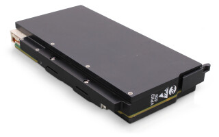
While this technology has been around for many years, now that there is a standard it enables a commercial off-the-shelf (COTS) approach for the military industry. VITA 48.7 (Air Flow-By), currently in the ratification process, is a configuration where the electronic card is sealed inside an external-finned heat sink. Cooling is provided by flowing air over the outside of the heat sink, which has the advantage of cooling both sides of the card components. This configuration is used in a standard card-cage rack and uses seals that are located in the backplane. Since this is a rack-mounted card, the vibration and shock levels are on the order of half when compared to VITA 48.5 and other conduction-cooled card chassis. Both of these air flow technologies have their place in military platforms and should be evaluated before selecting a system solution. An example of a VITA 48.5 system is GE Intelligent Platforms’ CRS 48.5 high performance embedded computing (HPEC) rugged system (shown in Figure 2) which contains four DSP280 cards, each featuring two Intel Core i7 processors, a switch card, a power-supply card, an EMI filter card, along with two spare slots; it all draws 1,200 W. The size and weight is similar to a 1 ATR long chassis.
Figure 2: GE Intelligent Platforms’ VITA 48.5 COTS Rugged System.
(Click graphic to zoom by 1.9x)
|
|

VITA 48.5 board and system-level design considerations
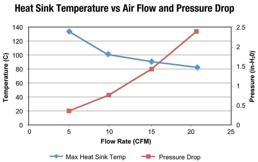
When designing a VITA 48.5 card, the air flow and pressure drop is left to the designer. A system integrator, of course, wants low pressure drop and low flow, so the challenge is to balance this desire in the heat-exchanger design. For cards that have 150 W of power draw, a target goal of 10 cfm flow and 0.7 in. H2O at 55 ºC ambient (20 cfm and 1.5 in H2O at 71 ºC) is achievable with this standard. Figure 3 shows how a designer might report performance of a card at one ambient temperature. This approach helps the system integrator size the system inlets and air routing because fans/blowers are selected using pressure-flow rate curves.
The VITA standard allows for either a 1.17" or 1.48" thick board assembly. The 1.48" thickness is needed when using mezzanine cards, which are attached to the opposite side of the heat exchanger as shown in Figure 1 (Front View). This setup is an excellent method of cooling a mezzanine card, since both thermal rails and card hot spots can be heat-sunk to the heat exchanger. If mezzanine cards are needed, this method reduces the air flow cross section in the metal work and increases the pressure drop when using standard 10 mm connectors. To increase the flow, a nonstandard connector is needed. Commercial connectors are available for a Switched Mezzanine Card (XMC) with an 18 mm board-to-board spacing and 15 mm for PCI Mezzanine Card (PMC), which helps, but this approach may not be optimum for a 1.48"-thick assembly that has a 25 mm board-to-board height. One method to get the 25 mm spacing is to use standard connectors on the boards and then use an interposer board or bridge connector. When designing with mezzanine cards, data is needed similar to Figure 3 for implementing in a chassis.
Figure 3: VITA 48.5 performance curve.
(Click graphic to zoom by 1.9x)
|
|
When designing a VITA 48.5 chassis, one option is to use the 1 ATR form factor. This form factor can replace older systems already on platforms, but the air flow is more restrictive in this orientation since the width of the chassis is defined by the ARINC 404 standard and does not provide enough wall space for a high-flow/low-restriction manifold. The routing of air from the front to rear can add an additional 10 percent pressure drop due to these narrow side walls and openings. A better approach is to apply the air inlet in the same direction as the card heat sinks using a header or manifold; the number of cards is then limited if trying to meet a 1 ATR form factor.
Balancing the flow rate through cards can be achieved by strategic placement and/or using orifices to route air through each card heat exchanger. This arrangement allows for maximizing card air flow while minimizing pressure drop. A good example of this is an integrated power-supply filter that occupies a slot in the chassis but has 70 percent less heat load than a graphics card. The amount of air flow can be reduced from 10 cfm to 3 cfm and more air flow can be routed to the graphics card. Ultimately, properly sized integrated military vaneaxial fans or external cabin air is needed for maximum performance.
Rugged military systems need rugged board solutions, and the cooling method has a big impact on the type of solution that can be used. Understanding how these system solutions work and the pros and cons of each is key to a successful platform that can work today and in the future.
Brian Hoden is Principal Mechanical Engineer, Embedded Engineering at GE Intelligent Platforms. He has more than 25 years of experience in military computer system designs, military laser system designs, telecommunication laser product manufacturing, and nuclear shipping container designs. Brian has also worked for Sandia National Laboratories, LATA, and Emcore, and holds a BSME degree from the University of New Mexico.
GE Intelligent Platforms, Inc. 800-433-2682 www.ge-ip.com